Introduction
Reliability and durability are essential in today’s competitive market place. However, component reliability verification tests and system durability tests take a long time, cycles, or miles to complete. This puts these tests in direct conflict with program timing, product development budgets, and limited testing resources. To minimize this conflict, it is essential to accelerate these tests.
Customer Duty Cycles and Mission Profiles
Organizations need to understand how the customer uses their product. This usage is often characterized as duty cycles. Similarly, the military will define a mission profile for their equipment. The basic problem is that the usage covers years of field usage. We don’t want to test a product for perhaps 10 years to certify that it is capable of providing 10 years of service.
One way to accelerate tests is to focus on product operation over the useful life. The useful life can be different for different products. One company specifies a 10 year useful life for the 95thpercentile vehicle as a design target. Data is available that shows the 95thpercentile vehicle is operated about 2 hours/day. Therefore, over a 10-year period, a vehicle will be operated about 7,300 hours out of a total of 87,600 hours. For components, like the engine and many vehicle electronic components, this represents a 12:1 reduction in test time. However, a remote engine start/stop, door lock/unlock, and alarm wireless module operates continuously.
Similarly, a missile will be stored for years before usage that may be as brief as a few seconds. One needs to consider how the missile ages during the extensive storage time.
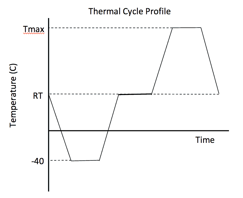
Another way to accelerate tests is to determine the time wasted in the test. For example, an automobile company specified an 8-hour thermal cycling test to verify solder joints were robust to extreme thermal cycles. The test chamber cycled from room temperature (RT), to -40C, back to RT, up to a maximum test temperature (Tmax), and back to RT. The test specified maximum ramp rates of 4C per minute. At each temperature, the product dwelled for 2 hour. This is captured in figure 1.

Figure 1
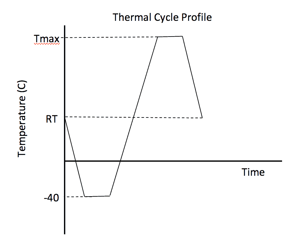
To identify wasted test time, the thermal response of an engine control module was measured in a thermal shock chamber. The internal module temperatures near the printed circuit board followed an exponential distribution.
- Instead of 2 hours, only 45 minutes of soak time was required for the module obtain equilibrium with the chamber temperature. Equilibrium was defined as being within 1C of the chamber temperature.
- The test was focused on thermal cycling so the 2 hour RT soak was eliminated. Other tests evaluating module performance at RT were available.
- The ramp rated was increased to minimize the ramp time.
The net result was the test cycle time was reduced from 8 hours to 4 hours, figure 2.

Figure 2
Accelerate Stresses
A way to reduce test time is to increase stress levels during the test. This method works until the higher stresses causes a new failure mode. The Physics of Failure for a failure mode of the part relates the aging of the part in the field to the aging of the part during a test. Some stress examples are
- Time at temperature aging.
- Thermal cycling
- Thermal shock
- Mechanical Vibration
- Mechanical shock
- Humidity
- Chemical Corrosion
Generally, a product development program specifies a suite of tests to verify product function and reliability. The Physics of Failure approach can be applied to many of the tests.
Electronic Engine Controller Thermal Aging
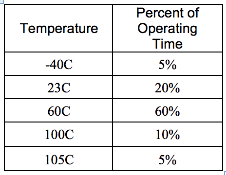
An electronic engine controller is mounted in the engine compartment of a vehicle where it operates at different temperatures. These temperatures are dictated by the local ambient conditions, the duration of the trip, and the engine loads. A proposed distribution of temperatures is captured in table 1.

Table 1
For a 95thpercentile customer operation of 7,300 hours, these operating percentages may be converted to time at the different temperatures. The physics of failure model that describes the aging of electronic components is the Arrhenius model, equation 1.
$$AF=e^{(E_a/k)(1/T_1-1/T_2)}$$
(1)
Here,
- Factor Eais the activation energy associated with a failure mode. For module level tests, a typical value is 0.4 is used.
- Factor k=0.00008617, is the Boltzmann constant.
- T1and T2are two temperatures, measured in Kelvin degrees. T1 would be the operating temperature, from the table. T2 would be the temperature used to thermally age the module
- AF is the acceleration factor for the test.
For the first data row, $-T_1=-40C=233.1K-$ and $-T_2=105C=378.15K-$. The acceleration factor associated with testing at 105C instead of -40C is 2068. The time at -40C was 5% of 7300 hours or 365 hours, then aging at -40C requires 0.176 hours at 105C. This calculation is repeated for each row, yielding table 2.

Table 2
The 10 year life requirement of 7300 hours for this engine controller has been reduced to 1873 hours, or about 78 days. For reliability test, this plan is reasonable.
Conclusions
Reliability and durability tests can be shortened by
- Identifying and removing non-operating time
- Removing waste time in a test cycle
- Use Physics of Failure models to focus the test on specific failure modes by increasing specific stresses.
Note
If you want to engage me on this or other topics, please contact me. I offer a free hour for the first contact to discuss your problem/concerns and to determine how I can help you.
I have worked in Quality, Reliability, Applied Statistics, and Data Analytics over 30 years in design engineering and manufacturing. In the university, I taught quality and reliability at the graduate level. I provide Minitab seminars to corporate clients, write articles, and have presented and written papers at SAE, ISSAT, and ASQ. I want to help solve your design and manufacturing problems.
Dennis Craggs, Consultant
810-964-1529
dlcraggs@me.com
 Ask a question or send along a comment.
Please login to view and use the contact form.
excellent article.
Thanks Don. A remaining problem is that the original tests were test-to-bogy, i.e., tests without failure. Testing to higher stress levels reduces the time to reach an equivalent bogy. I prefer test-to-failure because we learn about the product weakness when the root cause of failures are understood. Proposed design or manufacturing process changes can be make the product more robust. For example, an electromechanical switch was tested to failure and several design weakness were removed at no cost. But the product life improved by a factor of 6 to about 4 times the 95th percentile customer at the targeted design life. Much better results with test-to- failure than test-to-bogy.