Sizing liquid flow pipelines easily. Designing pipe work for liquid flow requires calculating the pressure losses along the pipe due to pipe friction. Once the losses are known the right pipe diameter can be selected. If full engineering calculations are not possible the conservative approach is to select pipe sizes that produce a velocity of less than 3 m/sec.
Keywords: pressure loss, viscosity, friction factor.
A ‘rule-of-thumb’ to use if you need to install liquid carrying pipelines without engineered drawings is to look for the largest supplying nozzle (usually a pump discharge or vessel outlet) and go up one standard pipe size for the main trunk line from the nozzle to the delivery point. For branches being supplied off the main trunk go up one pipe size if they are smaller than the main trunk line. Reduce down at nozzles and trunk line tees as necessary.
It is a handy rule-of-thumb but not the best way. The correct way to size liquid carrying pipelines is to calculate the pressure losses in the pipe from beginning to end.
NECESSARY REQUIREMENTS TO SIZE A PIPELINE
Pipe sizing depends on –
- Liquid velocity – fast flows have more pressure loss.
- Liquid viscosity (slipperiness) – the more viscous the liquid the more the friction. Temperature changes affect viscosity, usually decreasing with rising temperature.
- Pipe length – longer pipes have more pressure loss.
- Surface area – bigger diameters have lower velocities.
- Pipe wall roughness (surface finish) – rough pipes have more friction until complete turbulence is reached.
- Liquid vapour pressure – friction can cause such pressure loss the liquid boils and creates vapour bubbles.
- Presence of bubbles – gas bubbles take up space.
- Corrosive and erosive properties of the liquid – some liquids destroy piping at high velocities.
HOW TO CALCULATE PIPE SIZE
Engineers use the formula below (1) to calculate pressure loss in liquid carrying pipelines. Its use requires specialised knowledge. However an easier method is to assume a pipe velocity between 1m/s (3.25 ft/s) to a maximum of 4 m/s (13 ft/s) and use the much simpler second formula (2).
$$ \large\displaystyle\tag*{(1)} {{H}_{1}}=\frac{fl{{V}^{2}}}{d2g} $$
Where H1 is the head loss (m or ft)
f is the pipe wall friction factor depending on the liquid’s viscosity (dimensionless)
l is the equivalent pipe length (m or ft)
V is the liquid velocity (m/s or ft/s)
d is the pipe diameter (m or ft)
g is the gravitational constant (9.8 m/s2 or 32 ft/s2)
$$ \large\displaystyle\tag*{(1)} Q=VA $$
Where Q is the volume flow rate (m3/s or ft3/s)
V is the velocity (m/s or ft/s)
A is the area of the pipe bore (m2 or ft2)
Once the flow rate is decided or known, the pipe diameter can be calculated from the area. Minimise the cost of discharge pipelines by using smaller bore pipe with velocities at the high end of the recommended range. But to keep pressure loss low on suction piping use velocities from the lower end of the range.
WHERE PRESSURE LOSSES COME FROM IN PIPES
Liquid moving in a pipe has to push its way along pipe walls, around bends, through valves, past projections and enclosed items. Throughout its progress friction robs energy. Three factors that affect pressure loss in pipes.
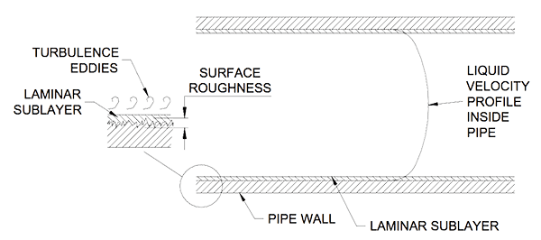
Surface Friction – Along walls the liquid has to overcome friction. Wall friction depends on surface roughness. The higher the projections into the liquid the more the friction. At low velocities a laminar sub layer of slow flowing liquid covers the roughness. But at high velocities the sub layer thins as the eddies in the turbulent center flow extends to the projections. Figure 1 shows the flow at the pipe wall.

Direction Changes – Liquid that is forced to change direction loses energy. When a liquid goes around a 90o bend its momentum has to be redirected. From going at velocity in one direction it now has to go at the same velocity in a completely different direction. To do this it converts pressure into the energy it needs to change direction. A pressure loss results. The more sudden the change in direction the greater the energy it needs and the higher the corresponding pressure losses.
Liquid viscosity – A liquid that easily slides requires less energy to move than one that does not want to flow. Honey is thousands of times more viscous than water. Pushing honey through pipes, around corners and past valves requires far more energy than for water. If the honey was warmed it would then flow easier and the pressure loss would be less.
MINIMISE FRICTION IN PIPELINE CONSTRUCTION
During design, procurement and installation of a pipeline follow the recommendations in Table 1.
| Design | |
|---|---|
| Select smooth bore pipes. | 100 meters of 100mm (4”) plastic pipe containing water moving at 1 m/s (3.25 ft/s) will lose 900mm (35”) of pressure. The same flow in a 100mm steel seamless pipe will lose 1000mm (39”) pressure. |
| Minimise flow disruptions. | Use long radius elbows; use pipe reducers; minimise the number of flanges; use full bore straight through valves; use pipe size branch tees and reduce down on the branch (a must on suction lines); use instrumentation which does not project into the flow. |
| Keep flow velocities low. | Select pipe sizes that are practicable while keeping flow velocities reasonable. |
| Construction | |
| Cut gasket holes to the bore diameter. | Make the gasket bore hole to the pipe bore diameter. Do not let the gasket project into the liquid flow path as it will cause unnecessary friction and turbulence. |
| Clean off weld splatter. | Weld splatter sits on the pipe surface and disrupts the liquid flow pattern. The splatter can come lose and damage down stream instruments and equipment. |
| Keep butt weld peaks low. | Like gaskets cut with the diameter less than the pipe bore, welds with high peaks project into the liquid flow. Try keep welds below the height of the sub- layer thickness. |
| Make multiple segment mitered bends. | ‘Lobster back’ 90° bends are used when large diameter long radius bends are not available. Make them out of equal sized 15° segments instead of the usual 22.5° segments |
Mike Sondalini – Maintenance Engineer
 Ask a question or send along a comment.
Please login to view and use the contact form.
It’s really interesting that splatter from the welded seams inside a pipe can actually disrupt the flow of the liquid. I can imagine that this issue compounds when you consider how long a pipeline can be and how many seams there must be. Keeping those welds clean could go a long way in maintaining pressure.