
Visual Inspections That Reveal Early Thermal Stress Damage
Thermal stress in components leads to premature failure. In the high-stakes world of industrial maintenance, the most dangerous failures are those that develop in silence. Thermally induced shaft damage typically does not announce itself with a sudden snap; rather, it matures through a progression of temperature gradients, mechanical constraints, and repeated thermal cycling. By the time cracks or permanent deformation become visible to the untrained eye, the window for low-cost intervention has usually closed.
Visual inspection and thermal imaging are both excellent non-destructive testing (NDT) techniques that detect impending failures early. In this article, we will discuss what to look for, what it means, and potential counter measures.
“Training site personnel to look for early indicators of thermal stress damage on shafts, couplings, and bearings is the single most effective way to prevent premature breakdown.”
The Genesis of Thermal Stress
Thermal stress in rotating machinery is rarely an isolated phenomenon. It is fundamentally an energy conversion problem. When
mechanical systems operate outside their design specifications due to misalignment, improper lubrication, or loading imbalances the kinetic energy that should be driving production is instead converted into waste heat.
The earliest stages of thermal stress are often invisible to the naked eye and undetectable by basic touch-tests. At the molecular level,
excessive heat begins to degrade the viscosity of lubricants, leading to a feedback loop where increased friction generates even more heat.
The 10°C Rule: In many electrical and mechanical insulation systems, every 10°C increase in operating temperature above
the rated limit can effectively halve the component’s remaining useful life (RUL).
Identifying the Early Signatures of Thermal Stress
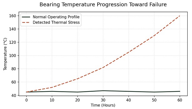
Modern predictive maintenance (PdM) relies on identifying the “inflection point” the moment when a component transitions from steady-state operation to an accelerated wear phase. Thermal signatures provide one of the most reliable indicators of this transition.
High-definition infrared thermography (IRT) allows technicians to visualize heat distribution across a bearing housing or motor
casing. An asymmetrical heat pattern often points to angular misalignment, whereas a uniform but elevated temperature profile
might suggest over-greasing or internal clearance issues.
thermal stress leading to bearing seizure.
Heat History Stamp: Heat Discoloration/Oxide Tinting
Heat discoloration / oxide tinting on shafts (and nearby nuts, washers, coupling hubs, keys, etc.) is a heat-history stamp. It forms when metal oxidizes after exposure to elevated temperature in the presence of oxygen. Once the oxide film is present, moisture accelerates corrosion; rust forms faster and adheres more aggressively. Tinting is therefore not cosmetic; it is evidence of a thermal event and a future corrosion risk.
Go to the Gemba:
Operators and technicians should be trained to identify failure fingerprints, escalate the issue when identified, and implement remediation procedures. During routine inspections, look for the following visual indicators of thermal stress.
Key Visual Indicators of Thermal Stress
- Heat discoloration or oxide tinting on shafts and nearby hardware
- Polished rub marks indicating transient bowing during operation
- Seal hardening, cracking, or glazing from elevated temperatures
- Uneven wear patterns on bearings and conveyor components
- Belt tracking drift that worsens at operating temperature
Color pattern is the clue:
Key Color indicators include:
| Observed Color | Interpretation |
|---|---|
| Straw / light gold tint | Mild overheating exposure; initial oxidation phase |
| Brown / purple | Moderate overheating; potential for lubricant degradation |
| Blue / deep blue | Significant overheating; serious thermal event requiring investigation |
| Patchy / one-sided tint | Localized hot spot (misalignment, rub, slip) |
| Tinting plus black soot / char | Severe heating or lubricant burning |
When to inspect immediately after reaching steady-state temperature, and again during cool-down (thermal contraction phase).
Where to focus shaft shoulders, bearing fits, seal lands, coupling hubs, keyways, and near heat sources (ovens/furnaces).
Note: Exact oxide colors vary with material, surface finish, and duration of exposure; use color primarily as a relative severity indicator.
Rule of thumb: If tinting is present, temperatures were high enough to change surface chemistry and may have altered lubrication performance, fits, or hardness locally.
Common Causes of Thermal Stress

- Overheating from Friction: Bearing running hot (lack of lubrication, wrong viscosity, over-greasing), tight/dry seal installation, or shaft rubbing on guards/housings.
- Electrical Damage: Tinting combined with fluting or pitting on bearing races can indicate shaft current discharge (often VFD-related).
- Thermal Gradients: Localized tinting can signal misalignment, thermal bow, or uneven cooling/heating cycles.
- Overload / Sustained Torque: Slip and micro-motion at the coupling hub or keyway region.
Confirmation of Potential Thermal Stress:
During investigation, evaluate the shaft and supporting components with the following questions in mind:
- Where exactly is the tinting? (bearing seat? seal land? coupling hub?)
- Does the thermal image show an image of a uniform thermal gradient or localized hot spots?
- Are there matching signs of friction (smearing/fretting) or electrical discharge (EDM marks/fluting)?
Quick Confirmation Checklist
- Temperature: compare IR readings across bearing housings, shaft ends, and coupling hubs at steady state.
- Fit / movement: check for fretting debris at hub/shaft interface and measure runout.
- Lubrication condition: inspect grease for darkening, bleeding oil, varnish smell, or hard crusting.
- Electrical: look for EDM frosting/fluting patterns; verify VFD grounding and shaft grounding path.
Thermal Stress Typically Correlates with (Failure Fingerprints)
If you see oxide tinting, it often pairs with:
- Blueing at bearing seat (inner race creep / loose fit)
- Smearing / galling at shaft seat
- Fretting corrosion (reddish/brown powder)
- Seal lip wear or melted seal material
- Coupling hub bore discoloration
Identifying Thermal Stress at Onset Using Acoustic and Thermal Correlation
When early detection is paramount, such as the case with critical A-class components, ultrasonic emission testing should be implemented as part of the PM strategy. While temperature is the symptom, ultrasonic emissions are often the precursor. Early friction creates high-frequency sound waves long before the mass of the metal housing warms up enough to be detected by external sensors.
Conclusion
Thermal stress is a silent killer of components compromising their structural integrity and lifetime. When operators and technicians are trained to identify failure fingerprints, escalate the issue when identified, and implement remediation procedures components have a higher probability of maximizing their RUL.
Join us on our YouTube channel for the free lecture: Thermal Expansion & Shaft Failure — Explained! 🔥 LS-005
Next Article: Temperature mapping & thermal imaging interpretation

Leave a Reply