Plant and equipment do not fail by accident. There are causes. Whether equipment fails depends on the capacity of their parts to handle stresses, when stresses are applied and the size of those stresses. These are probabilistic events – they are random, with many possibilities. Timing the start of failure, or its continuation to a breakdown, is mostly speculation because it depends on which past and future scenarios occur. It seems that luck and chance has a large say on the lifetime reliability of equipment. But there is a way to guide equipment reliability and performance toward the results you want.
Keywords: random failures, quality management system, equipment reliability,
Randomness, probability, likelihood, chance – the more we learn about them, the more we come to realise how much they impact our lives, our businesses1 and our machines, plant and equipment. All around us things happen to our machines and equipment. People make choices and act. We only see the effects of those choices in the future. Often we can’t differentiate one effect from another because past choices interact and react, to the point that unknown and unknowable events happen. Operators, maintainers, manufacturers, engineers, managers, purchasing officers, suppliers, and many others make choices all the time that impact the lives and reliability of our plant and equipment. Because so many people are involved and, over time, so many things can happen, our machines are seemingly at the mercy of luck and fortune.
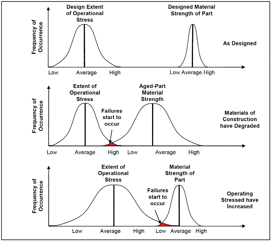
The top curves in Figure 1 show a distribution of the strength-of-material used in a part, alongside is the distribution of expected operational stresses the item is exposed to. The equipment designer’s role is to select material for a part with adequate strength for the expected stresses. If the equipment is operated and maintained as the designer forecasts there is little likelihood that the part will fail and it can expect a long working life because the highest operating stress is well below the lowest-strength part’s capacity to handle the stress. The gap between the two extremes of the distributions is a factor of safety the designer gave us to accommodate the unknown and unknowable.
However some parts do fail and the equipment they belong to then stops working (First parts fail, then machines stop). Certain causes of equipment failure are due to the aging of parts, where time and/or accumulated use weakens or removes the materials of construction. This is shown by the middle curves of Figure 1 where the parts’ material properties are degraded by use and age until a proportion of the parts are too weak for the imposed loads, and they fail. In other cases operating stresses change and overloads are imposed on parts. The bottom curves in Figure 1 represent this situation. The range of operating stresses has grown, and in some situations they are now so large that they exceed the material strength of the part, and failures occur.
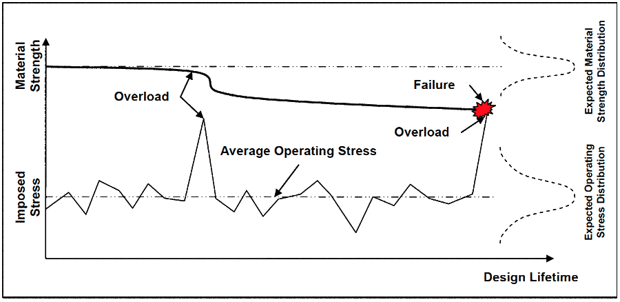
Figure 2 shows how induced stresses lower the capacity of materials of construction to accommodate future overloads. A portion of the material strength is lost with each high stress incident until the last high stress incident occurs which finally fails the part. Figure 2 also highlights the failure prediction dilemma – the timing and severity of overload incidents is unknowable – they may happen and they may not happen. It seems a matter of luck and chance whether parts are exposed to high risk situations that could cause failure. These excessive stresses are not necessarily the fault of poor operating practices. In fact they are unlikely to only be due to perator abuse. They are more likely to be due to the acceptance of bad engineering and maintenance quality standards. More about this follows later in the article.
Limits of Material Strength
The materials of which parts are made do not know what causes them stress. They simply reach to the stress experienced. If the stress is beyond their material capacity, they deform as the atomic structure collapses2. Materials-of-construction suffer structural damage at the atomic level when concentrated overload stress occurs. The greatest stress occurs when the load is localised to a very small area on a part. Once a failure site starts in the atomic matrix it will progress and grow larger whenever sufficient stress is present. The stress to propagate a failure is significantly less than the stress needed to generate the failure. At a highly localised stress concentration point any applied stress is multiplied by orders of magnitude3. Like a bone once broken is weakened forever, once a crack failure site isinitiated even normal operational loads can be sufficient to lead to premature art failure. The operating lives of roller bearings are a case in point, but this explanation of failure applies to all lubricated metal-to-metal dynamic contact situations such as gears, vane pumps, and hydraulic pumps.
Depending on the lubricant regime (hydrodynamic, elastohydrodynamic), viscosity, shaft speed and contact pressures roller bearing elements are separated from their raceways in the load zone by lubricant thickness of 0.0254 to 5 micron. Eighty percent of lubricant contamination is of particles less than 5 micron size5. This means that in the location of highest stress, the load zone, tiny solid particles can be jammed against the load surfaces of the roller and the race. The bottom diagram in Figure 3 shows a situation of particle contamination in the load zone of a bearing.
Figure 3 shows a solid particle carried in the lubricant film of the bearing squashed between the outer race and therolling element. Like a punch pushing a hole through a sheet of steel, the particle causes a high load to be concentrated in the small contact areas on the race and roller. The surfaces may or may not be damaged by the particle depending on the size of stress developed (a probabilistic event). Low and average stresses may be accommodated by the material-of- construction. However an exceptionally high stress means the atomic structure in the contact point area on the rolling element and raceway can be damaged, generating surface and subsurface sub- microscopic cracks6. Such exceptionally high stress can result from the cumulative combination of the intended design load carried by the bearing supported on a jammed particle, plus operational abuse of the equipment, plus impact loads from the misalignment of shafts, plus tightened clearances caused by overheated bearings, plus forces from out-of-balance masses, along with numerous other possible stress-raising incidents. These events are probabilistic – they might randomly happen at the same time and place, or they may not. If they do happen together they also might or might not coincide with damaged locations. Whether an overload from misalignment, tight clearances, operator abuse, out-of-balance, etc. actually happens at the same time and place as a contaminant particle is jammed between the surface of the roller and race is a matter of chance.
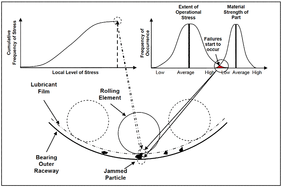
Table 1 lists some of the ISO 4406 – ‘Hydraulic Fluid Power – Fluids – Method for Coding the Level of Contamination by Solid Particles’ range numbers. As the range number rises there are more particles in the same millilitre of lubricant (a millilitre is a volume equal to about 20 drops of distilled water). Each increase in range number is twice the number of particles of the previous range. As the number of contaminating particles present in a bearing’s lubricant increases, then the possibility that particles are available to be jammed between load zone surfaces rises. In contaminated lubricant there are plentiful opportunities for metal surfaces to be failed.
Lubricant with a range number 21 (dirty lubricant) has 125 times the number of particles in each millilitre thanlubricant with a range number of 14 (clean lubricant). It can be implied from Table 1 that the likelihood of failure from particle contamination is greater as range numbers increase. The risk of failure rises because there is ever increasing numbers of particles. But failure is not certain because many other factors influence the stresses produced in a situation. You could have very clean lubricant, and though the odds are extremely small, you may be unlucky enough to jam the only particle in the neighbourhood between roller and race at the same time as a rotating misalignment force vector passes through it.
When a roller bearing is in use the rolling element turns and any damaged area moves away from the load zone. The possibility of that area on the roller again being damaged reduces considerably because the roller is always turning to a different spot, and for the same spot to come into the load zone when a particle is there, ready to be jammed into the damaged surface, is a low probability. However, the damaged area on the race does not turn away and remains exposed to all rolling elements that pass over it in future. In highly contaminated lubricant the chance is higherthat a particle is present when another rolling element arrives over a previously stressed area of a race to again be jammed into that surface, possibly extending any sub-microscopic damage.
Range NumberNumber of Particles per MillilitreIncrease inParticle Count from 10 RangeVisual Colour25160,000320,00032,000 |
Table 1 – ISO 4406 Particle Count for Lubricant
The extent of contamination allowed in lubrication directly impacts the likelihood of roller bearing failure7. Often companies with black oil in their gearboxes, drives and bearing housings will replace lubricant when an oil analysis indicates contamination is too high, or it is replaced on time- based preventative maintenance. Because they replacethe lubricant it falsely appears that they have prevented lubricant particle contamination failures. Unfortunately, by the time lubricant becomes dark from particle contamination the probability of jamming a particle between two contact surfaces has markedly increased. To significantly reduce lubricant contamination failures the particle count must be kept below or at clear levels so the oil never gets dark from particle contamination. Changing dark oil is far too late to greatly reduce the probability of failure. The oil must never get darkened by particle contamination in thefirst place if you want to control the influence of luck and chance on your lubricated and hydraulic equipment.
Need for Engineering and Maintenance Standards
If shaft misalignment is present on equipment it does not mean that a bearing will be failed. Depending on the extent of misalignment, and the size of the operating loads, the resulting stresses may still be lower than the bearing’s material-of-construction strength. But it does mean that any misalignment increases the chances that its resulting loads will combine with those caused by, perhaps, a jammed contaminant particle and add to the stress seen by the race. The same probabilistic scenarios can be said of operational abuse, internal clearance reduction caused by high temperatures, out-of-balance forces from unbalanced masses, and a myriad of other stress-raising possibilities.
Reducing the influence of chance and luck on equipment parts starts by deciding what engineering and maintenance standards you will specify and achieve in your operation. For example, what number of contaminating particles will you permit in your lubricant? The lower the quantity of particles, the higher the likelihood you will not have a failure. What balance standard will you set for your rotors? The lower the residual out-of-balance forces, the smallerthe possibility that out-of- balance loads will combine with other loads to initiate or propagate failures. How accurately will you specify fastener extension for critical connections to prevent fasteners loosening or breaking? The more precise the extension meets the needs of the working load, the less likely a fastener will come loose, or be overloaded, and a connection fail. These are probabilistic outcomes that you can influence. By specifying the conditions and standards that produce excellent equipment reliability and performance you will begin to turn luck and chance in your favour.
The degree of shaft misalignment tolerated between equipment directly impacts the likelihood of roller bearing failure8. The frequency and scale of machine abuse permitted during operation directly affects the likelihood of roller bearing failure. The standard achieved for rotating equipment balancing directly influences the likelihood of roller bearing failure9. The temperatures at which bearings operate change their internal clearances, which directly influence the likelihood of roller bearing failure10. The same can be said for every other factor that affects the life of a roller bearing. Similar statements about the dependency of failure on the probability of failure causing incidents can be said of every equipment part. Chance and luck determine the lifetime reliability of all parts, and consequently all your machines and rotating equipment. But the chance and luck seen by your equipment parts is malleable. They can be reduced by removing the causes of failure.
For example, you can select cleanliness limits that greatly reduce the number of contaminant particles in lubricant11.With far fewer particles present in the lubricant film there is marked reduction in the possibility that particles will be jammed between load zone surfaces. Combine that with ensuring shafts are closely aligned at operating temperature, that rotors are highly balanced, that bearing clearances are correctly set, that operational abuse is banded and replaced with operating practices that keep loads below design maximums, as well as reducing the many other adverse factors affecting equipment part-life, and you will greatly improve your ‘luck’ with equipment reliability.
Need for Work Quality Management System
Yet how will you ensure the failure-reducing standards will be used and met? How will you turn the words in the standards and specifications into real actions that deliver the desired results? You can write tombs on how to get reliable equipment, but that does not produce reliable equipment. Only competent people working to quality controlled processes will deliver equipment reliability.
Selecting and setting standards is only the start of the process of delivering fewer failures. The standards must then be applied and used in managing the risks seen by your equipment. They must move from being good ideas, to becoming clear, documented intentions, and finally put into real practice on the plant and equipment. This is the purpose and function of a quality management system (QMS).
A QMS prevents adverse chance and limits the consequence of those events that it cannot stop. A QMS that extends across operator practices and guides them in the proper use of equipment, that controls rotor balance to low values, ensures shaft alignment is exact, that delivers low lubricant particle contamination, helps tradespeople get fastener tensions right, etc. will produce highly reliable equipment. It removes the chance of bad things happening. Where it cannot reduce chance, it limits the downside. The cumulative stresses of random incidents are lower. For example, once situations of balance, cleanliness, alignment, steady operation, looseness, clearances, etc. are controlled to precision levels it will not matter when they arise or how they arise, because it will be unlikely that they can add together to create high stress situations; they do not have a great capacity left in them to produce damage. This is how chance and luck in your operation is controlled and managed.
Your business processes must be changed to ensure the standards that deliver low probabilities of failure are applied in your operation. Your workplace processes, along with the associated engineering, operating and maintenance practices, must be upgrade to meet those standards. It is by first causing reductions in the likelihood of failure that high lifetime reliability can later be realised. By introducing standards that produce low chances of causing failure, training to them, managing to them, promoting by them (thereby creating role models), and enforcing them you reduce the influence of luck in your business. You may still get very occasional equipment failures, because unforeseen random failure causes can arise. But the failures will become less and less as the possibilities that cause them are removed by your world-class engineering, operating and maintenance practices.
My best regards to you
Mike Sondalini
1 Mlodinow, Leonard, The Drunkard’s Walk – How Randomness Rules Our Lives, Allen Lane (Penguin Books), 2008
2 Gordon, J. E., The New Science of Strong Materials or Why You Don’t Fall Through the Floor, Penguin Books, Second Edition, 1976
3 Juvinall, R. C., Engineering Considerations of Stress, Strain and Strength, McGraw-Hill, 1967
4 Jones, William R. Jr., Jansen ,Mark J., Lubrication for Space Applications, NASA, 2005
5 Bisset, Wayne, ‘Management of Particulate Contamination in Lubrication Systems’ Presentation, IMRt Lubrication and Condition Monitoring Forum, Melbourne, Australia, October 2008
6 FA17G OEM und Handel AG, Ro640lling Bearing Damage – recognition of damage and bearing inspection, Publication WL82102/2EA/96/6/96
7 SKF Ball Bearing Journal #242 – Contamination in lubrication systems for bearings in industrial gearboxes,1993
8 Piotrowski, John., Shaft Alignment Handbook, 3rd Edition, CRC Press, 2007
9 ISO 1940-1:2003 Mechanical vibration — Balance quality requirements for rotors in a constant (rigid) state — Part 1: Specification and verification of balance tolerances
10 FAG OEM und Handel AG, Rolling Bearing Damage – recognition of damage and bearing inspection, Publication WL82102/2EA/96/6/96
11 ISO 4406-1999 Hydraulic Fluid Power – Fluids – Method for Coding the Level of Contamination by Solid Particles

Leave a Reply