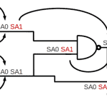
When I introduced you to the Stuck at Fault Model I stated that the size of VLSI devices necessitated the usage of Electronic Design Automation (EDA) tools to support testing.
My first full-time job at IBM exposed me to the world of test and to their EDA tools.
In the mid-1980’s, testing of logic devices relied upon the S@ fault model. Three common software tools included fault simulation, automatic test pattern generation, and fault diagnosis.
This article will provide an introduction to fault simulation as one can view the other two tools as applications built upon a fault simulator.
Fault Simulator Components
Engineers created fault simulators to deal with the complexity that computer devices (computer boards and silicon devices) held due to their size and the need to manufacture good parts. One can manually do a fault simulation on a logic gate and with some effort a small combinational circuit such as an adder. You may have noticed the tedium in performing the propagation of faults to an observable output. Hence, this is an ideal task to let a computer do the work for you.
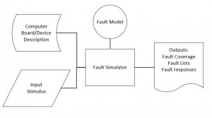
In the diagram below illustrates conceptually the inputs, the fault model and the outputs.
S@ Fault Simulator Goals
Fault simulators perform the analysis with a specific representation of the Device Under Test (DUT). The S@ model most often has been applied at the logic gate level as introduced in the previous articles. Naturally, you could apply this at the transistor and interconnect level. The fault simulator needs to compile a list of faults based upon the DUT description and the fault model used. This diagram assumes you already have a set of input stimulus to assess. With such a stimulus the simulator needs to assess how the faulty versions of the circuit behave. You can consider the S@ fault simulator as an optimized case of a logic simulator. It needs to be more efficient than a logic simulator as it performs not only good DUT simulation but many faulty DUT simulations.
Goals of the fault simulator include: assessing the percentage of model faults detected by the applied stimulus, providing the faulty responses per input stimulus per fault modeled. Creating the fault list is a straight forward process. At its core a fault simulator propagates faults through the provided netlist. The efficiency of fault simulators depends upon maximizing learnings as you apply a stimulus to your netlist. The effectiveness of the fault simulator can be assessed in terms of netlist size, ability to parallelize analysis of multiple faults and the compactness of the results.
Metrics for S@ Fault simulators
You’ll often hear that the S@ fault coverage for a set of test vectors is 95.5%. This is the most common metric because it’s the question that everyone wants to the answer for. There are some other metrics that are useful in understanding improvements: faults not detected, redundant faults.
Reminder on Model Limitations
The S@ fault model has been around since the 1950’s and applied extensively in the early days of computers and VLSI devices. While knowing the S@ fault coverage of test patterns is necessary today it is not sufficient assessment of what is needed to test modern electronics. The underlying electronics technology has changed significantly over the decades: single Bipolar transistors to CMOS VLSI devices to Deep SubMicron devices. Manufacturing defects differ for each of these technologies and have morphed over the years. The S@ fault model does not reflect accurately how all defects can manifest into faulty electrical behavior. Over the last three decades there’s been an evolution of fault models used in digital testing. Stay tuned for articles later this year that will inform you more on this topic.
Are you enjoying what you have been learning at Testing 123? Do you think that your co-workers would benefit from learning more? Then consider contacting me about training tailored to your company’s needs.
Meanwhile remember testing takes time and thoughtful application,
Anne Meixner, PhD
You can find course notes from university classes on VLSI testing on line. The course notes from Dr Andre Ivanov’s EECE 578 class Integrated Circuit Design for Test (2008) provide a good introduction.
In 1966 John Paul Roth described one of the first algorithms for fault propagation. For one of my masters’ classes I took a class on test taught by Dr. Roth. He taught an informative class in which we had to program in a language of our choice a test related algorithm. I chose to teach my self APL for this assignment. He often brought in a camera to take a picture of the whiteboards as he taught the class.
Abstract: The problem considered is the diagnosis of failures of automata, specifically, failures that manifest themselves as logical malfunctions. A review of previous methods and results is first given. A method termed the “calculus of D-cubes” is then introduced, which allows one to describe and compute the behavior of failing acyclic automata, both internally and externally. An algorithm, called the D-algorithm, is then developed which utilizes this calculus to compute tests to detect failures. First a manual method is presented, by means of an example. Thence, the D-algorithm is precisely described by means of a program written in Iverson notation. Finally, it is shown for the acyclic case in which the automation is constructed from AND’s, NAND’s, OR’s and NOR’s that if a test exists, the D-algorithm will compute such a test.

 Ask a question or send along a comment.
Please login to view and use the contact form.
Leave a Reply