
A fault tree analysis (FTA) is a logical, graphical diagram that starts with an unwanted, undesirable, or anomalous state of a system.
The diagram then lays out the many possible faults and combination of faults within the subsystems, components, assemblies, software, and parts comprising the system which may lead to the top level unwanted fault condition.
An FTA shows the many possible cause and effect paths to a specific fault condition.
For example, a laptop computer may have a top-level fault of not turning on. A few possible causes are a dead battery, faulty power distribution circuitry, or a broken power switch.
By graphically portraying the various paths to the top level fault you may be able to:
- Identify ways to improve the system reliability by improving critical elements of the system
- Quickly identify the root cause of an actual fault by using the FTA to evaluate each potential cause
- Using boolean algebra calculate the probability of the fault occurring overall and via each potential path
- Provide an alternative view of system performance with a focus on one particular fault at a time
- Uncover potential unwanted interactions, adverse secondary faults, and impact of human interaction of system behavior
A team activity
The development of an FTA should be accomplished by a team.
While an individual could construct a fault tree, bringing a group of individual with deep knowledge of the various elements of a system will result in a comprehensive fault tree.
Furthermore, the team gains the insights through discussion of system response to potential faults. This may result in the identification of additional experimentation or modeling to fully characterize system behavior. Or, it may reveal potential improvements to the design or improved mitigation to potential faults.
The initial construction of the fault tree should take place early in the system development process. Ideally, the initial work begins just as the basic system architecture and essential functions are defined.
As the system development defines subsystems and specific components, the team should refine the FTA and use the tool as a guide to avoid increasing the probability of the top level fault occurring.
If the FTA occurs too late in the development process it will have little impact on the development and improvement of the system reliability.
Elements of a Fault Tree
A fault tree is a top-down, graphical, logical model depicting the various ways a specific fault may occur and is made up of specific logic symbols.
The logic gates provide a means to relate the various lower level faults as they progress to the occurrence of the top level fault.
There are three groups of symbols useful when constructing a fault tree.
- Event symbols: Events are conditions or faults and the symbols indicate if they are normal, independent, conditional, or contributing. Generally the lowest level faults in the analysis.
- Gate symbols: Gates depict the basic functional relationship in logic form and used to connect lower level events which contribute to the upper-level events or faults.
- Transfer symbols: Transfer symbols provide a convenient means to connect related fault trees, including fault trees of a subsystem to its system.
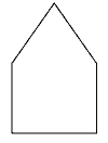
Common event symbols


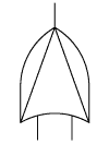
Common gate symbols


Common transfer symbols


Symbols and descriptions from:
Fault tree handbook with aerospace applications. Office of safety and mission assurance NASA Headquarters, 2002.
Related:
Basic Approaches to Life Testing (article)
Reliability Testing (article)
The Next Step in Your Data Analysis (article)

Leave a Reply