
Much of what we do in engineering and maintenance we accept without question. People say, ―It‘s been done that way for decades,‖ implying that it must be correct. But for equally as many decades have come stories of failed and broken machinery, plant and businesses. On one hand we continue to unquestioningly do what has been done for generations, yet on the other hand we cannot stop equipment failing. There is a subtle connection between the two of which we are only just becoming aware. The connection is obvious when you realise that we have been running our businesses by risk and luck, and not on facts and understanding.
Keywords: process variation, equipment failure, failure root cause
Probability, likelihood, chance: the more we learn about them, the more we realise how much they impact our lives, our businesses and our machines1. All around us things happen. People make choices and act. We only see the effects of those choices in the future. Often we can‘t differentiate one effect from another because past choices interact and react to make unknown and unknowable events happen. Operators, maintainers, manufacturers, engineers, managers, purchasing officers, suppliers, and many others, make choices all the time that impact the health and reliability of our plant and equipment. With so many unknowables going on around us, our machines, our businesses and our lives are seemingly at the mercy of luck and fortune.
The great misunderstanding is that having a process in-place to do a thing never guarantees a right outcome. Unseen vagaries produce variability: the cause of most operating and business problems2. Variability is ‗the range of possible outcomes‘. A business does not want its operations producing out-of-specification merchandise and wasting money, time and effort. A highly variable business process (a business process includes its people, its documents, the selection process, the training performed, the work environment, the materials used; everything that affects the outcome) allows results to range across good, mediocre and occasional disaster. This process is out-of-control—volatile—and if it is an engineering or maintenance process then failures and equipment breakdowns are built into the business. When a process design is volatile the outcomes cannot be guaranteed, some will be right and some wrong; like playing a roulette wheel at a Monte Carlo cassino. Volatility maybe random, but it is no accident: there are causes.
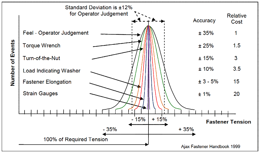
An example of a classic misunderstanding of variability that makes equipment breakdown is the tightening of fasteners. It is the root cause of many flange leaks, loose connections and machine vibration problems. Figure 1 shows the variation in the typical methods use to tighten fasteners3. The method with greatest variation, ranging ± 35%, is ‗Feel-Operator Judgement‘, where muscle tension is used to gauge fastener tension. Even using a torque wrench has a variation of ± 25%, unless special practices are followed that can reduce it to ± 15%.
The standard deviation for the “Feel” method is ± 12%. This means if fasteners tightened by ‗Feel‘ are required to be within ± 10% of correct tension (a figured arrived at by the Author on the realisation that those companies he knew that used load indicating washers no longer had fastener problems) then only about 60% of them are within tolerance, with the other 40% having great opportunity to cause problems. It is impossible to guarantee accuracy when tightening fasteners by muscular feel. Using a process that ranges ± 35% to get within ± 10% of a required value is playing a game of chance. Every fastener in the world tightened by “Feel” is at risk.
Those companies that approve the use of operator judgement when tensioning fasteners must also accept that there will many cases of loose fasteners and broken fasteners. It cannot be otherwise because processes that use muscle-induced torque to tension fasteners have a high amount of inherent variation. It would be a very foolish manager or engineer who demanded that their people stop fastened joint failures, but only allowed them to use operator feel, or tension wrenches, to control the accuracy of their work. Such a manager or engineer might come to believe that they have poorly skilled and error-prone people working for them, when in reality it is the process which they in ignorance specified and approved that is causing the failures. They misunderstand totally that it is the process which is not accurate enough to ensure correct fastener tension. It is not the people with the spanners who are causing the failures.
Joint failure is inherent in the muscular-feel process. Torque is a poor means for ensuring proper fastener tension. To stop fasteners failing needs a process that delivers a required shank extension. The fastening process must be changed to one that guarantees the necessary fastener stretch. Only after that management decision is made and followed through by purchasing the necessary technology, quality controlling the new method to limit variation, and training the workforce in the correct practice until competent, that the intended outcome can always be expected. The use of operator feel when tensioning fasteners is a management decision that automatically leads to breakdowns. Any operation using people‘s muscles to control fastener tension has failure built into its design – it is the nature of the process.
The operating lives of roller bearings are another example where the effects of random chance and luck are not considered by managers and engineers when they select their maintenance strategies and engineering practices. Another old custom used without concern is the process of replacing roller bearings on shafts and into housings. A work order is raised for a bearing replacement and the job gets done. Usually no one wonders how well the bearing was installed. The right fits and tolerances are critical to the correct clearance between roller and race for long, failure-free life. Figure 2 shows the effect that changes in clearance have on the life of a 50mm ball bearing. Clearly, an overload or under-load condition in a roller bearing, regardless of how it arises, will cause early failure. Any loss of design clearance is unforgiving to bearing life, especially when roller and race are forced together with greater than pre-load force.
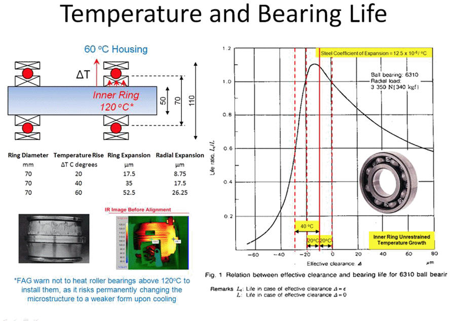
Superimposed over the roller bearing clearance life curve are thermal growth lines showing the change in clearance for each 20 °C difference between inner and outer race. In normal operating conditions, the differential temperature between inner and outer races varies from 5 °C to 10 °C4. But greater temperature differentials are possible when a race is exposed to a large cooling effect or a large heat source, or if it is damaged or run in a way that generates excessive heat. Examples of how that much temperature difference can arise is shown by the misaligned motor thermal image and the spalled race. When the differential temperature between races is substantially hotter than the design intended, the added expansion forces the roller into the race, causing a rapid fall in bearing life. If the temperature differential allows the clearance to expand it also leads to early failure, but less rapidly. A necessary operating condition to get full roller bearing life is to ensure they run at design temperatures and see no unforeseen temperature differentials.
Bearing life is also fatally impacted when the clearance is wrongly set at installation. A race installed on a too-tight shaft, or into a too-tight housing, causes rapid loss of bearing life. Figure 2 highlights the importance to roller bearing life of getting the correct interference fit on the shaft and in the housing. It warns us that any error in roller bearing fit means sure early bearing failure. A loose fit is not so severe, but maximum bearing life cannot be achieved. The right differential temperature must be developed across the bearing and the bearing must be fitted to a correctly sized shaft and a correctly sized housing. Companies that allow roller bearings to be replaced without correctly measuring the shafts and housings with micrometers, and the result checked against the bearing manufacturer‘s required fit and tolerance for the operating situation (not for the bearing, as it is common for bearings to be wrongly selected for the actual operating situation) are running by gosh and by golly. Any bearing replacement process that does not ask for proof of correct bearing clearance selection, correct differential temperature control and correct fitting accuracy, by default allows bearing clearance errors to occur from human error, and people ought not to be surprised at the subsequent bearing failures that must happen.
The common maintenance practice of changing oil after it is black is another engineering and maintenance process decision that designs failure into equipment.
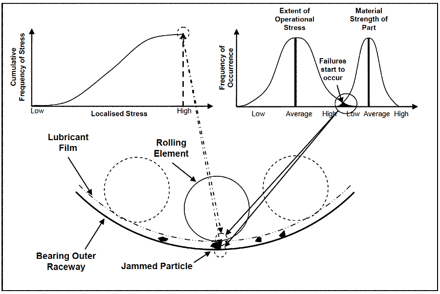
Depending on the lubricant regime (e.g. hydrodynamic, elastohydrodynamic), viscosity, shaft speed and contact pressures, roller bearing elements are separated from their raceways in the load zone by lubricant thickness of 0.0255 to 5 micron. Eighty percent of lubricant contamination is of particles less than 5 micron size6. This means that in the location of highest stress, the load zone, tiny solid particles can be jammed against the load surfaces of the roller and the race. The bottom diagram in Figure 3 shows a situation of particle contamination in the load zone of a bearing. A solid particle carried in the lubricant film is squashed between the outer raceway and a rolling element. Like a punch forcing a hole through sheet steel, the contaminant particle causes a high load concentration in the small contact areas on the race and roller. Depending on the size of stress developed, the surfaces may or may not be damaged by the particle. Low and average stresses are accommodated by the plastic deformation of the material-of-construction. However an exceptionally high stress punches into the atomic structure, generating surface and subsurface sub-microscopic cracks7. Once a crack is generated it becomes a stress raiser and grows under much lower stress levels than those needed to initiate it8.
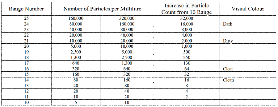
The amount of contamination in lubricant directly impacts the likelihood of roller bearing failure9. Table 1 lists some ISO 4406 oil contamination range numbers10. Each number has twice the count of solid particles in a millilitre of lubricant (a volume equal to about 20 drops of distilled water) as the previous range. Lubricant with a range number 21 (dirty lubricant) has 125 times the number of particles in each millilitre than a lubricant with 14 (clean lubricant). It can be implied from Table 1 that because the availability of particles to be punched into load zone surfaces, or to block oil flow paths, or to jam sliding surfaces rises, the chance of equipment failure from particle contamination is greater as the oil gets dirtier.
When a roller bearing is in use the rolling element turns but the race stays still. The possibility that a damaged area on a roller is repeatedly stressed is low because the roller is always moving to a different spot. However, a damaged area on the race remains exposed to all rolling elements that pass over it in future. The chance of bearing spall, where the surface metal of a race lifts and breaks-off (like a pothole on a road), rises with greater oil contamination. But surface failure is not certain until sufficient stress is present to cause cracks.
Exceptionally high stresses can be caused by cumulative loading where loads, each individually below the threshold that damages the atomic structure, unite. Such circumstances arise when a light load supported on a jammed particle then combines with additional loads from other stress-raising incidents. These incidents include impact loads from misaligned shafts, tightened clearances from overheated bearings, forces from out-of-balance masses, and sudden operator-induced overload. All these stress events are random. They might happen, or they may not happen, at the same time and place as a contaminant particle is jammed into the surface of a roller. Whether they combine together to produce a sufficiently high stress to create new cracks, or they happen on already damaged locations where lesser loads will continue the damage, are matters of probability.
The size and frequency of stress seen by a bearing depends on many random factors. You could have very clean lubricant, and though the odds are extremely small, you may be unlucky enough to jam the only particle in the neighbourhood between roller and race at the same time as a rotating misalignment force vector passes through it. We can be sure that as lubricant gets more contaminated, the chance to spall a bearing race increases. With each rolling element that arrives over the load zone the growing number of particles provide ever increasing opportunity for one to be punched into the surface. The risk of failure carried by a company‘s plant and equipment from oil contamination is the direct result of the management processes applied (or not applied) to decide how much contamination will be sanctioned in their oil. When management decide to replace lubricant only when it is dirty they have unwittingly agreed to let their equipment fail.
Companies mistakenly allow gearbox, bearing and hydraulic system oils to get dirty and blacken from wear particles before changing the oil. Often waiting for an oil analysis to indicate high contamination, or replacing dirty oil on time-based maintenance. Unfortunately, by the time lubricant becomes dirty from particle contamination, the probability of jamming a particle between two contact surfaces has markedly increased and failure sites may already have been initiated in roller bearings (or similar high elastohydrodynamic situations, such as gear teeth). To significantly reduce bearing failures, gear failures and sticking hydraulic valve problems, the particle count must be kept at clear levels, or below, so the oil never has many contamination particles in it. Changing black oil is far too late to greatly reduce the probability of failure. The oil must never be darkened by particle contamination in the first place if you want to reduce the influence of luck and chance on your lubricated and hydraulic equipment breakdowns.
Many managers, supervisors and engineers are fervent that their company has the right maintenance practices and excellent preventive maintenance processes in place. If their processes include any of the ‗normal‘ customs described above, they are of course wrong, because from time to time those processes naturally produce breakdowns. This is why W. Edwards Deming said his famous warning to managers, ―Your business is perfectly designed to give you the results that you get.‖ Poor equipment reliability is the result of choosing to use maintenance and engineering processes that have inherently wide variation. These processes are statistically incapable of delivering the required performance with certainty, and so equipment failure is a normal outcome of their use and must be regularly expected. Failure is designed into these processes and luck plays a great part in keeping the equipment operating. The failure of equipment is directly related to the volatility inherent in the processes selected to purchase, maintain and operate the plant and machinery.
Businesses still use engineering processes long believed to be suitable, not comprehending that these processes naturally contain inherent volatility that make their equipment fail. Are you trying to achieve impossible results using engineering and maintenance processes with inherent variation outside the performance you need? Trying to improve production equipment reliability using maintenance and engineering customs that naturally produce failure outcomes, is an exercise in futility. It will cause great waste, produce distress for all concerned and lead to emotional burn-out for the managers, engineers and supervisors involved. The only approach that can work is to change to a process where all its outcomes are what you want.
Mike Sondalini
References
1 Mlodinow, Leonard, The Drunkard‘s Walk – How Randomness Rules Our Lives, Allen Lane (Penguin Books), 2008
2 Deming, W. Edwards, Out of the Crisis, MIT Press, London, England, 2000 edition
3 Fastener Handbook – Bolt Products, Page 48, Ajax Fasteners, Victoria, Australia, 1999 edition
4 Ball and Roller Bearings Catalogue, 2202 II/E, NTN Corporation
5 Jones, William R. Jr., Jansen ,Mark J., Lubrication for Space Applications, NASA, 2005
6 Bisset, Wayne, “Management of Particulate Contamination in Lubrication Systems” Presentation, IMRt Lubrication and Condition Monitoring Forum, Melbourne, Australia, October 2008
7 FAG OEM und Handel AG, “Rolling Bearing Damage – recognition of damage and bearing inspection”, Publication WL82102/2EA/96/6/96
8 Juvinall, R. C., Engineering Considerations of Stress, Strain and Strength, McGraw-Hill, 1967
9 SKF Ball Bearing Journal #242 – Contamination in lubrication systems for bearings in industrial gearboxes,1993
10 ISO 4406 – ‗Hydraulic Fluid Power – Fluids – Method for Coding the Level of Contamination by Solid Particles‘

Leave a Reply