What readers will learn from this article.
- The purpose of pressure relief valves.
- How pressure relief valves work.
- The correct way to install relief valves.
- Selection and testing issues for pressure relief valves.

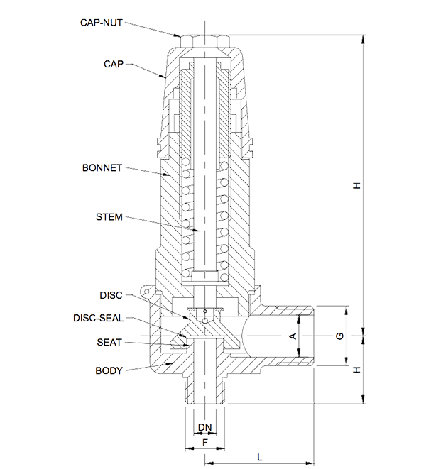
A pressure relief valve (PRV) is used to prevent over-pressure in a vessel or pipeline. It consists of a disk pushed onto a seat by a spring. The seat is forced open with the rising pressure and relieves the build-up.
The contact faces of the seat and disk are machined smooth and accurate so no leakage occurs when the process pressure is less than the set pressure. The set pressure is the pressure at which the valve opens. If the pressure rises above the set pressure the force on the disk pushes the spring up and the valve vents.
PRV’s are sized to insure that when they vent, the pressure in the equipment they are protecting against rupture does not rise much above its design pressure. Selecting an undersized sized PRV can lead to a catastrophe and special calculations are required to determine the right size for the application.
A PRV is mounted directly to a connection on the vessel or pipeline it protects. This can be a flange or a screwed socket. As it is always in operation protecting against over-pressure, no isolation valves are permitted between it and the process. If the valve requires removal due to process contamination, statutory requirements or maintenance the entire process must be shut down and made safe.
In situations where this is not possible two correctly sized PRV’s are used side-by-side, mounted on a common manifold with an internal valve that always leaves one of the PRV’s connected to the process.
PRV’s should always be oriented so the inlet port stays clean and cannot be blocked by process contamination. Usually they are mounted vertically. Where vertical orientation is not possible the nozzle is extended and brought vertical. A PRV mounted on its side in a liquid environment will most likely block. Chose materials of construction for PRV’s that are not corroded by galvanic action between dissimilar metals or process chemicals.
The outlet of a PRV is to be kept clear right through to the discharge point. The ends of the vent pipe must to grated to stop birds nesting inside the pipe. The discharge pipe outlet must be oriented so rainwater cannot build up above the valve. If a head of water is sitting on the valve disk the process pressure must rise high enough to lift both the spring and the water. A simple precaution is to drill a 3mm (1/8”) drain hole in the discharge pipe just after the PRV outlet with a drain piped away to remove water or discharged liquid.
When PRV’s are tested they are mounted on a test rig and pressurised under controlled conditions with water or compressed air till the disk lifts. The lift pressure is recorded and adjustments are made to the spring tension if the set pressure is in error. After any adjustments the PRV is again tested to insure it lifts at the correct pressure.
PRV selection is based on its ability to vent the contents at a sufficient rate to prevent the vessel from bursting. To insure minimal pressure drop along the inlet or outlet pipe it should be kept short. The pipe diameters must be of at least the same nominal diameter as the respective valve nozzles. If a long discharge line from the valve outlet is necessary use a pipe at least one diameter larger than the outlet nozzle size to minimise back-pressure.
Remember that when a PRV vents a gas or steam into much a lower pressure than at the inlet the gas or steam will expand many times its previous volume. The large increase in volume generates a high velocity through the pipe in order to get the gas away. There will be a lot of high- pitched noise and large volumes of vapour and liquid discharged.
Mike Sondalini – Maintenance Engineer
If you found this interesting, you may like the ebook Process Control Essentials.
 Ask a question or send along a comment.
Please login to view and use the contact form.
We have define the lift of Pressure relief valve(spring type).
How to calculate the value of lift? Analytical or Graphical ?
Can you do the needful.