The concept of derating is similar to the mechanical engineering concept of a stress–strength analysis.
The intent is to ensure that the selected component or the mechanical design has sufficient strength to withstand the expected applied stresses.
Components operating at or near their rated values have short lives. Consequently, the general practice is to use components for materials well below their rated values to extend the operating life of the items.
This is where derating comes into play.
Apply derating deliberately
The ability to make informed decisions concerning derating includes understanding the relationship between derating and the time to failure (TTF).
For a given set of components that have publicly available TTF studies, along with recommended derating guidelines, this paper examines a way to display the derating recommendations and the TTF information in a single plot.
The ability to view the relationship along with the derating policy enables decisions concerning the selected component derating value’s impact on component reliability.
This has the advantage of enabling one to efficiently consider design tradeoffs including costs, size, performance, and reliability.
Applying derating deliberately in a well-informed manner enhances the system reliability performance.
The ability to quickly understand the impact an applied stress and the component rated values have on the TTF allows the selection of the right component.
Adhering to derating policies, selecting components less responsive to the applied stress, and making comparisons are additional benefits.
Visualizing the relationships does require additional information than is commonly provided, yet it provides value in a compact form.
Temperature relationship to time to failure
Using a capacitor at less than rated temperature does provide a reduction of temperature-related stress within the capacitor.
This reduces the dielectric and lengthens the time to failure:
$$ \displaystyle\large \frac{{{t}_{1}}}{{{t}_{2}}}=\exp \left[ \frac{{{E}_{a}}}{k}\left( \frac{1}{{{T}_{1}}}-\frac{1}{{{T}_{2}}} \right) \right],$$ (1)
where t1 is the time to failure (characteristic life) for the capacitor in its application, t2 is the expected time to failure for the capacitor when used at its maximum rated temperature, T1 is the application or applied temperature in kelvins, T2 is the maximum rated temperature in kelvins, Ea is the activation energy, and k is Boltzmann’s constant (8.62 × 10⁻⁵ eV/K).
At the vendor-recommended voltage derating of 80% the activation energy, determined empirically, is 1.37 eV/K.
Therefore, solving for t1 given t2 of 2,000 hours, we find for an application temperature of 50°C an expected life of 2,560,000 hours, or an approximate 1,280 TTF multiplier.
An alternative plot for derating information
Having performed the calculations above for just two voltage values leads into the more general concept of visualizing the relationship among the applied voltage, maximum rated voltage, and expected lifetime.
Using the data-sheet-recommended 80% derating as the baseline, we can normalize the change in lifetime by dividing the calculated t1 for the actual voltage divided by the calculated t1 for the nominal derating expected life.
This means that the TTF multiplier is 1 when we select a component with a derated value that matches the applied voltage.
When the applied voltage is below the recommended derated voltage (21 Vdc instead of 24 Vdc in the above example), we can calculate the beneficial impact on reliability.
If the applied voltage is above the recommended derated voltage, we can determine the reduction in reliability.
Figure 1 shows the TTF multiplier for a range of ratios of operating voltage to maximum rated voltage.
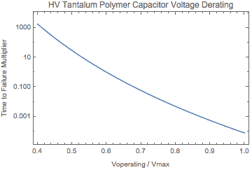
Figure 1 – Plot of TTF multiplier vs Vop/VmaxAt 0.8 (80%) operating voltage over maximum rated voltage, the TTF multiplier is equal to 1. At a higher derating value, the multiplier is Figure 2 shows the impact of operating temperature on the TTF multiplier
At 0.8 (80%) operating voltage over maximum rated voltage, the TTF multiplier is equal to 1.
At a higher derating value, the multiplier is Figure 2 shows the impact of operating temperature on the TTF multiplier
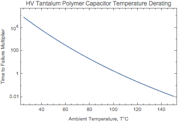
Figure 2 – Plot of TTF multiplier vs operating temperature.
According to Kemet, the derated temperature is 105°C. Operating at 50°C provides a multiplier of 1,280 or improvement to the expected TTF duration. The base expected endurance at 105°C is 2,000 hours.
Figure 2 shows the TTF relationship for temperature based on the TTF model created by Reed and Haddox [6].
They used an Arrhenius equation with an activation energy of 1.37 eV/K.
Using the derating plot to make decisions
Derating to TTF plots are useful in a number of ways: they provide a visual display of derating policy related to permissible changes to derating as they impact TTF.
- They provide a visual display of derating policy related to permissible changes to derating as they impact TTF.
- They help identify derating policy violations.
- They facilitate the selection of less-stress-dependent components
- They enable a comparison of vendor and internal derating to TTF impact.
There may be other benefits, yet the key is the improvement in decision making by the design engineer and review teams.
Being able to directly estimate the impact on TTF for each derating decision enables reliability performance considerations to be immediately included in each decision.
The ability to forecast actual field reliability performance depends on factors beyond those considered in reliability modeling and prediction approaches.
The relationship between the derated stress and TTF remains intact.
Visual display
Visualizing the normalized TTF values removes the absolute need to focus on the TTF value itself.
Instead, the plot of derating or stress versus TTF multiplier reveals the impact a change in relative stress imparts on the expected reliability of the component.
Derating policy
Modifying the plot to include derating policy further enhances the derating plots.
If the policy is to avoid halving the nominal TTF (doubling the failure rate) then one can add a shaded region to the plot as seen in Figure 3.
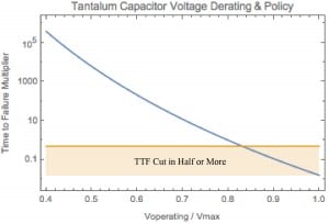 

Figure 3 – Plot of TTF multiplier vs Vop/Vmax showing a shaded region to indicate half of the nominal TTF or less.The yellow line represents the policy.
With approximately 83% or higher derating, the TTF multiplier will be 0.5 or less.
The yellow line represents the policy. With approximately 83% or higher derating, the TTF multiplier will be 0.5 or less.
One could also add keep-out zones dependent on the specific technology.
For example, electrolytic capacitors do not operate well with very low derating.
Stress dependency
The slope of the curve relates to the relative influence a change in applied stress imparts on the TTF multiplier.
A steep slope implies a strong influence of the stress on the component TTF, whereas a shallow slope implies that the component TTF is little influenced by a change in the applied stress.
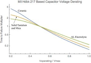
Figure 4 – Plot of TTF multiplier vs Vop/Vmax. for four types of capacitors.
Each capacitor has a slightly different response to the applied voltage [7].
Ceramic capacitors with the steepest curve indicate they are affected by temperature more than the other capacitor types.
Derating and TTF comparisons
Different vendors use different formulas or processing to improve the performance of their components.
Comparing data sheet information alone may not provide sufficient information to determine which component is appropriate for a specific application.
Obtaining and plotting the TTF multiplier versus stress (derating factor) sufficiently enables the comparison.
The relative shapes, curvatures, and slopes indicate differences in the response each component provides for a change in applied stress.
References
1. “KEMET Organic Capacitor (KO-CAP (R) —Industrial, T521 High Voltage Polymer Electrolytic, 12.5 – 75 VDC”, http://www.kemet.com/Lists/ProductCatalog/Attachments/252/KEM_T2016_T521.pdf accessed 20 July 2016.
2. From the Capacitor section of the SD-18 http://www.navsea.navy.mil/Home/Warfare-Centers/NSWC-Crane/Resources/SD-18/Products/Capacitors/Derating/, accessed 20 July 2016.
3. S. R. Robertson, et.al..SMC-S-010 (2013) Technical Requirements for Electronic Parts, Materials, and Processes Used in Space and Launch Vehicles. Aerospace Corporation, Systems Planning and Engineering Group, 2006, pg. 81.
4. Sahu, Kusum, Henning Leidecker, and Darryl Lakins. 2003. “EEE-INST-002: Instructions for EEE Parts Selection, Screening, Qualification, and Derating”, NASA/TP-2003-212242.
5. “IPC-9592 Performance Parameters for Power Conversion Devices.”. IPC-9592 performance parameters for power conversion devices. IPC.
6. Erik Reed and George Haddox. 2011. “Reliability of high-voltage tantalum polymer capacitors.” CARTS USA 2011, 28-31.
7. MIL-STD-217 Reliability Prediction of Electronic Equipment. MIL-HDBK-217F Notice 2, 28 Feb 1995.
8. IEC/TR 62380:2004(E) Reliability data handbook – Universal model for reliability prediction of electronics components, PCBs, and equipment. 2004. Geneva, Switzerland: International Electrotechnical Commission.
This article is an excerpt from an upcoming I’ll be presenting at RAMS 2017 in Orlando, FL
 Ask a question or send along a comment.
Please login to view and use the contact form.
Leave a Reply