What readers will learn from this article.
- Overview of how a programmable logic controller (PLC) operates.
- Communication methods used to connect the PLC to equipment.
- Dangerous practices that will lead to trouble if not corrected.
A process logic controller is a computer designed for monitoring and controlling equipment. The personal computer that many people have at home is designed to accept signals from the keyboard or mouse and use instructions (software) to display the resulting effects on a screen (monitor). A PLC accepts signals (inputs) from sensors located throughout a piece of equipment or process plant. It then follows the instructions (program) within its memory and sends out commands (output) to operate equipment.
Inside the PLC
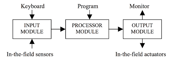
Modern PLC’s are a modular construction of electronic components on circuit boards that individually plug into place. There are four basic parts – the Input Module (input card), the Processor Module (CPU), the Output Module (output card) and the Power Supply. The heart of a PLC consists of the processor module. It receives signals from the input module and then follows the program to generate signals that are sent out by the output module. Figure 1 is a simple overview of a PLC’s interactive functions.

Humans interact with a PLC by use of monitors and keyboards. Special programming panels with a keyboard and screen connect to the PLC and allow the control program to be put into its memory. When the PLC is in use humans view its instructions and the resulting actions by a screen monitor. This can be mounted on the control room desk or near the equipment being controlled. A keyboard or mouse is used to give a command signal to the PLC when it is operating.
Connecting the PLC to the World Outside
The PLC is a computer and operates with digital instructions in binary code of ‘0’ and ‘1’. However field sensors produce an electrical signal in proportion to the effect they are monitoring (analogue signal), while the field actuators operate either by electrical or pneumatic (air pressure) means. The PLC must receive binary information to use the control program and perform the required instructions. The analogue electrical signals must be converted into digital signals and digital signals into analogue electrical signals. This is the function of the input and output cards (the I/O).
The input module converts a sensor’s electrical signal into its binary equivalent (digital signal). While the output module does the opposite and generates an analogue electrical signal, from the digital instruction provided by the PLC, that go to the field actuators. Interconnecting all the sensors, PLC and actuators is the communication cabling.
The data communications cabling carries low voltage electrical signals. These signals are the means by which the PLC interacts with the equipment it controls. The data cable does not provide the electrical power to move actuators. A separate power supply is provided to the actuator for its operation. Instruction signals from the PLC need to activate an individual item of equipment. At present there are three commonly used methods to transmit signals between the PLC and the field sensors and actuators to activate the equipment.
In one case the signal is sent to a switch in a local control panel (LCP) which then turns on and the electrical power is sent to the field item down its own dedicated cables coming from the LCP. A relatively new innovation is to have communications cabling in one loop around the plant with the various sensors and actuators connected onto the loop. Each item has its own identification code (ID) or ‘tag number’. The PLC receives and sends signals prefixed with the item code. The field item with the required code is activated when it recognises its ID and powers-up to perform the attached instruction. The third method for transmitting instructions is by the use of telecommunications. In this case the PLC is located in a different geographic location to the equipment it is commanding. Instructions are sent by radio to the remote site. Electrical power to operate the equipment is provided at the site.
Issues with Using PLC’s
The PLC is inseparable to the safe operation of the plant and equipment. Without the PLC the plant cannot be safely run. It is possible to configure the PLC so it can be removed from its controlling function and the whole plant operated manually. This may be a useful feature to jog and test individual equipment after repair but it is a dangerous practice to run plant in manual when the PLC fail-safes and protection are inactive.
Very few control software programs work properly on their first installation into the PLC. Most times they require some degree of modification under field conditions. Unless the field signals are properly interpreted by the PLC and its instructions are then properly sent and properly received by the field actuator, a fault will occur. Often it is necessary to install sensors on the field equipment to actually confirm the instruction has been performed.
Ad-hoc (spur of the moment) control program change is another dangerous practice to adopt. Often when a plant is operating it becomes clear that if it worked in a slightly different way it would perform better. So the required changes are quickly and suddenly made to the program and the plant put back in service. Many times the change affects something else that was not recognised as being affected. Suddenly the plant’s operation is in jeopardy. Ad-hoc program changes lead to trouble, each change must be thoroughly investigated and tested by plant knowledgeable persons before it is made permanent.
Keep a copy of the new and old programs. Every time a change is made to a program three things must be done. First the reason for the change and the results of the investigation must be permanently documented for auditing and traceablility. Secondly a copy of the new program with the changes must be made and kept in a safe place away from risk of damage. Thirdly a complete copy of the program prior the change must be kept so the plant can be put back into its previous configuration should the new program change cause problems.
Standardise on the PLC to be used throughout the plant. A PLC requires support from people to do repairs on its parts and to modify its program. It takes much effort to become proficient (to master) in supporting a PLC. If there are more than one type of PLC on site then two sets of spares are required and two sets of training and two programming panels are needed and two lots of program copies must be kept. If someone then buys in a third type of PLC for a new plant the problem of support becomes monstrous. The answer is to standardise on one PLC supplier.
Mike Sondalini – Maintenance Engineer
If you found this interesting, you may like the ebook Process Control Essentials.
 Ask a question or send along a comment.
Please login to view and use the contact form.
This article offers a clear and concise explanation of Programmable Logic Controllers (PLCs), making complex concepts accessible. It effectively highlights the importance of PLCs in industrial automation and their role in enhancing operational efficiency.