What you will learn from this article.
- The types of forces developed in a turning agitator.
- Gearbox position and configuration for long-life.
- Bearing arrangements to minimise gearbox loading.
- Simple, strong agitator support arrangements.
- Vapour seals are needed to stop fumes escaping.
- Lots of low maintenance selection and design tips.
Agitated vessels and tanks are common throughout the process and chemical industries. A properly sized agitator with correct proportions to suit the tank will deliver well-mixed product. A correctly sized gearbox with well-chosen bearings and bearing arrangements will need only regular lubrication while giving years of trouble free service.
Forces on Working Agitators
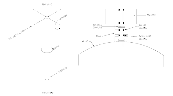
Figure No. 1 shows a conceptual sketch of an agitator shaft rotating in a tank. Arrows are used to show the forces that act on the agitator. Forces act downward due to self-load and the weight of product. Forces also act upward due to lift generated by the turning paddles or blades (just like a boat’s propeller pushes it through the water). Forces acting sideways occur from any out-of-balance motion of the shaft and from the propeller action creating random eddies spinning off the blades. All these forces must be countered through the bearings in the gearbox and those on the shaft.

Free-hanging agitators, unsupported by a bearing at the bottom of the shaft, suffer bending moments from the side-ways thrust forces. These moments try to bend the shaft towards the wall of the tank.
The bearings in the gearbox take all this side thrust loading. One way to reduce the gearbox radial loading is to install intermediate bearings at the top of the shaft and let them take the side-ways and vertical loads. These shaft bearings also take any ‘bouncing’ axial forces from uneven mixing. The second drawing in Figure No. 1 shows positions of intermediate bearings.
Blades, Baffles, and Agitator Positions
The blades, paddles or propellers are turned fast enough to generate a downward current towards the bottom of the tank. The current fans out when it hits the tank bottom and surges towards the walls. It flows up the walls taking the contents along with it. At the surface of the liquid the current collapses and drops into the middle of the tank where the turning blades again draw it down. The blades are made to turn fast enough to pick-up any solid ingredients in the mix. These upward flows are occurring at the same time as the agitator rotates the mixture.
When an agitator is mounted in the center of the tank it is best to position three or four baffles evenly spaced around the tank wall. Baffle plates down the wall of the tank set up an even flow pattern which removes random eddies generated by the blades and minimises fluctuating loads. The baffles load-up the agitator blades more evenly. The baffles also create eddies that peel off the edges for the full height of the baffle producing vigorous mixing of constituents. Baffles greatly improve and speed-up mixing. Without baffles a conical dead zone occurs directly below the agitator where the ingredients collect and do not mix.
In tanks where baffles cannot be installed it is best to locate the agitator at a 1:2 distance off the wall. Putting the agitator a third of a diameter from the wall creates unequal flow patterns that impact against each other with unequal force and allows one flow to shear through the other and produce more thorough mixing.
Agitator Support Arrangements
Small agitators and mixers are often inserted into the tank at an angle and clamped to the tank wall. When a vertical agitator is required the mounting frame for the agitator must be solid, sturdy and stiff enough to take all the transmitted forces and moments without visibly flexing. Suppliers of agitators can advise the sizing and arrangement of mounting frame members to handle the loads taken by their equipment.
Where an agitator is to go into a metal, open-top tank it is usual to put it on steel beams spanning the tank. Compensating plates are welded to the outside of the tank at the top of the wall to stiffen it. Steel supporting feet are then welded to the compensating plates and the cross-members spanning the tank are bolted to the support feet. For plastic tanks the support structure needs to go to the floor and be well anchored and braced to take the flexing forces.
For roofed tanks the frame can either be mounted in the same fashion as an open top tank or the frame can be mounted to the roof. The roof will need to be sufficiently thick and well supported to take the transmitted forces and moments without visibly flexing. Mounting a live load to a tank roof requires a thorough engineering analysis of the tank structure to insure it is structurally sound.
Agitator Removal
It is bad practice to expect people to go into a tank to unbolt blades from an agitator shaft so the shaft can be removed. People who go into a confined space are putting their lives at risk. It is better to insure the complete agitator and blade assembly can be removed through the top of the tank without anyone having to go inside. Insure the full length of the agitator can be removed without interfering with neighbouring plant along side or above. If a mobile crane cannot access the tank to remove the agitator and gearbox a fixed hoist will need to be installed.
Vapours from Closed Agitated Tanks
Where vapours are generated inside an enclosed stirred tank or vessel it is necessary to provide a seal around the agitator shaft to prevent vapours entering the gearbox through failed shaft seals. The vapour seal comprises a tall-sided annulus full of liquid (usually water) with the shaft rising up through the center hole. An inverted ‘dish’ with long sides extending into the annulus is attached onto the shaft and turns with it. The height of the walls on the inverted dish and annulus are made long enough so the vapour pressure in the tank does not push the liquid out of the vapour seal.
The liquid in the seal will become contaminated with the tank vapour and will require occasional replacement and replenishment.
Maintenance Issues with Tank Agitators
Below is listed a number of equipment longevity issues that need to be addressed when selecting and installing tank agitators:
- Access is required to shaft couplings. Gearboxes need to be stood up off framework to allow access for hands and tools.
- Select shaft couplings and components that will tolerate fluctuating axial loads and vapours from the process.
- Methods to get gearboxes off the agitator and lowered to the ground must be designed in at the start.
- If corrosive chemicals are used in the process it is necessary to address materials compatibility issues within the liquid and the vapour space.
- Use of chains and vee-belts in the drive arrangement lead to trouble. They get dirty and wear fast. Horizontally mounted chains sag and wear sprocket teeth away. Repairs become an expensive and difficult job.
- By installing bearings on the agitator shaft to take the axial and bending forces it is possible to go use a less expensive gearbox than one specially designed for agitators. The bearings take all the shaft loads and the gearbox just takes the torque loads.
- Insure the bearing arrangement in the gearbox, and any intermediate steady bearings in combination, can handle both axial and radial loading.
- Where the agitator is unrestrained at the bottom all the loads should be carried by the upper bearing arrangement and not by the gearbox. If the gearbox is required to take operating loads insure the bearings are substantial, well spaced and well lubricated.
- If a bottom steady bearing is installed, the tank height and bottom access should be designed so the bearing can be dropped without entering the tank.
- If a bottom steady bearing is installed it must accurately line- up with any intermediate bearings in the top of the tank or with the bearings in the gearbox. It is absolutely critical to insure the top bearings line-up with the bottom steady bearing in order to prevent excessive wear of the spigot and journal.
- If a bottom steady bearing is installed with a journal and spigot design (plain bearing design) select journal materials that wear out before the spigot so the need for a vessel entry is reduced.
- If the gearbox is a critical piece of equipment it must be placed on a condition-monitoring regime. Either bearing vibration analysis or oil contamination analysis is the minimum requirement. The choice of monitoring method depends on the site situation. Only one monitoring technique is sufficient.
- The bearings will require lubrication and a means to replenish lubricant. This needs to be installed from the start.
- If a suspended agitator shaft is required, where possible, install a self-centering blade design near the bottom of the shaft.
Mike Sondalini – Equipment Longevity Engineer
References: N Harnby, MF Edwards, AW Nienow, Mixing in the Process Industries, Butterworth-Heinemann, 1985
If you found this interesting, you may like the ebook Process Control Essentials.
 Ask a question or send along a comment.
Please login to view and use the contact form.
Leave a Reply