Vibration from out-of -balance rotating equipment can be frightening.
The ground shakes, machines jump about, hold down bolts come loose and parts break.
An unbalanced rotating body will produce forces on its bearings and transmit them throughout its structure and into the foundations.
Keywords: rotor, centrifugal forces, balance quality.
Causes for unbalancing
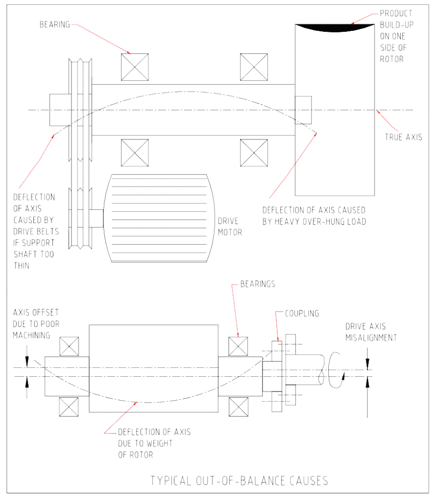
The table below lists some common causes for unbalance.
- a) Bent or bowed between support bearings
- b) Overhung weight bends shaft under gravity
- c) Unevenly distributed solid or liquid inside rotor
- d) Loose parts on the rotor
- e) Eccentrically manufactured diameters on the rotor
- f) Misalignment of the drive train to the rotor axis
- g) Loose drive couplings flop about
- h) Loose tolerances between assembled parts on rotor
- i) Shoulders on rotor manufactured out-of-square to axis
- j) Voids or cavities within the rotor
- k) Misalignment of bearings force shaft to bow
The drawings below provide examples of some of the problems listed in the table above.
Reducing out-of-balance problems
Minimizing vibration involves minimizing out-of-balance forces.
The following table indicates simple actions to take to reduce the problems of out-of-balance.
i) Make the rotor with all diameters on the same axis
ii) Machine the rotor from one piece of material
iii) Machine the rotor complete without altering the initial machining set-up
iv) Finish machine multiple part rotors when fully assembled on the shaft
v) Reduce lengths of unsupported sections and overhangs vi) Keep tolerances tight on parts assembled on the rotor vii) Align the drive train to the axis of the rotor carefully viii) Ensure the bearing supports are aligned
Balancing rotors
An out-of -balance machine can be made to run smoothly by balancing the rotating parts to within acceptable limits.
Balancing is the process of attempting to improve the distribution of mass in a body so that it rotates in its bearings without unbalanced centrifugal forces.
It can only be attained to a certain degree.
When a part is to be balanced it is necessary to specify the quality of balance required. The more precise the balance required the higher the cost to attain it.
Relevant standards have been set for various types of components.
The list below is taken from BS 6861 and shows typical grades of balance for common components.
Balance Rotor Types – General Examples Quality:
- G4000 Drive trains of slow marine diesel engines
- G1600 Drive trains of rigidly mounted large two-cycle engines G630 Drive trains of large four-cycle engines
- G250 Drive trains of fast, rigidly mounted diesel engines G100 Complete assembled engines of cars, trucks, and locomotives
- G40 Car wheels, wheel rims, wheel sets, drive shafts G16 Propeller shafts, individual car engine components, crushing machine parts
- G6.3 Fans, pump impellers, electric motors, general machinery parts
- G2.5 Gas and steam turbines, computer disks, machine tool drives
- G1 Grinding machine drives, tape recorder drive
- G0.4 Precision grinder spindles, gyroscopes
Attaching or removing weight at relevant points on the rotor permits balance corrections.
For example, specifically weighted tags can be welded to the rotor, or metal can be removed by drilling holes into the rotor at relevant positions.
To minimize the possibility of vibration problems, specify to the machine shop the degree of balance quality required of the part.
To improve the accuracy of balancing send all the attached assemblies such as couplings, bolts, keys, and pulleys with the rotor so the effect of the components can be allowed for in the balance corrections.
Mike Sondalini – Maintenance Engineer
DISCLAIMER: Because the authors, publisher, and resellers do not know the context in which the information presented in the articles is to be used, they accept no responsibility for the consequences of using the information.
If you found this interesting, you may like the ebook Pumping Basics.

 Ask a question or send along a comment.
Please login to view and use the contact form.
Leave a Reply