In the previous article you learned to apply the Stuck at Fault Model (S@) to a small combinational circuit.
You can take the learning on the Full 1-bit adder and apply it to larger combinational circuit.
In testing lingo, you often hear people refer to this as the testing of random logic. Technically, there’s nothing random about the logic.
I think “random” gets used to contrast with the highly structured design of memory circuits into array of 1-bit cells. Memory test lends itself to algorithmic testing, for example the Marching 1. In random logic testing you may use algorithms to propagate your faults, that is automatically develop a test pattern.
You need to keep in mind that the logic being tested has a functional purpose and this can be implemented in a multitude of ways. Let’s take a second look at the adder function.
A 4 Bit Adder
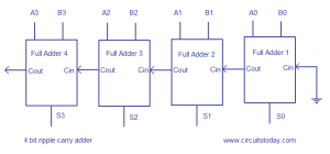
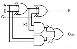
With a 4-bit adder you can calculate the efficiency of S@ fault vs functional testing. The 4-bit adder has 8 inputs and 5 outputs (you may observe that the Cin signal is grounded on the first bit). To functionally test this circuit with all possible inputs, you need 2**8 inputs, i.e. 256 test vectors. Looking solely at the inputs and outputs to the adder circuit you have 2 x13 S@ faults to test– 26 tests. This assumes that there is no fault collapsing. There probably such collapsing, though, to fully apply S@ testing you need to know what’s inside the adder block. In the last article, you propagated faults through the adder design shown below.
Each adder has 3 inputs, 3 internal nodes and 2 outputs. A total of 16 S@ faults per 1-bit adder. With four 1-bit adders you have a total of 64 S@ faults to detect. Fault collapsing would result in less than 64 tests. As this is a tedious manual analysis you need to use a fault simulator know the minimum number of tests. You can take advantage of the regularly in the adder design, i.e. 4 identical blocks. You analyze the faults in one adder and what the tests could be and use these to determine the total number of tests to get you a full 100% S@ fault coverage.
Different Adders
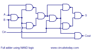
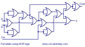
Now suppose you worked with a circuit technology that didn’t have exclusive ORs. Then you may have a different implementation and hence a different number of stuck at faults. Consider a full adder implemented with only NAND gates or only NOR gates as depicted below. How many S@ faults do you need to consider now for the 4-bit adder?
Check your result s against the table below.
| Adder implementation | Internal Nodes | Signals per adder | Total Number of signals | Number of S@ faults |
| XOR and AND | 3 | 8 | 32 | 64 |
| NAND | 7 | 10 | 40 | 80 |
| NOR | 9 | 12 | 48 | 96 |
Approach for Logic Stuck at Fault Testing
I chose to use a familiar function, the adder, for exploring S@ fault testing to provide you several learning opportunities. First, you gained a sense of fault propagation by manually determining how to propagate faults to the output of the adder block. By expanding from 1 to 2 and then to 4-bit adders you have some numbers to easily compare the functional test approach to a S@ approach to testing. Comparing all possible inputs against detecting all S@ faults one can see that even without fault collapsing which approach wins with efficiency. Now I’ll be honest, I am biased towards stuck at faults. You also could see how hierarchy could be used and how there could be differences in the adder blocks which changes the number of S@ faults you need to detect.
When approaching an electronics device with over one million logic gates, the scale of the solution just builds upon looking at one logic gate. As William Mulholland, LA aqueduct mastermind stated “The man who has made one brick can make two bricks. That is the bigness of this engineering problem. It is big, but it is simply big.” That’s really where fault simulation comes in handy. An introduction to terminology and approaches will be provided in the next article.
Meanwhile remember testing takes time and thoughtful application,
Anne Meixner, PhD
The implementations of adders were taken from an article in circuits today.


 Ask a question or send along a comment.
Please login to view and use the contact form.
Leave a Reply