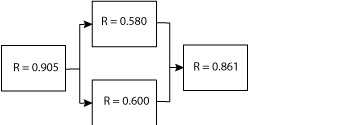
A reliability block diagram is a graphical and mathematical model of the elements of a system permitting the calculation of system reliability given the reliability of the elements.
The model reflects the reliability performance structure including series, parallel, standby and other arrangements of system elements.
Each block in an RBD represents a component or subsystem of the system. The organization and connecting lines represent the reliability structure of the system and may or may not be representative of the system’s functional block diagram.
This simple graphic is a basic RBD with 4 subsystems the R values are the probability of success (reliability) values for that element over a specific time period.

In complex systems, the RBD model in Figure 1 may be a summary of the major subsystems. Each subsystem may have an associate RBD with its own diagram of its subsystems and components. Include sufficient detail with each RBD (system or subsystem level) to support decision making.
For example, there is no need to show every component on a circuit board when the decisions under consideration do not include any changes to the circuit board itself.
Approach
The basic building blocks include series, parallel, k-out-of-n and complex (a mix of the other structures) structures.
Essentially the model represents the reliability structure of the system. If the system fails when any one element fails, then it’s a series system. If there are redundant power supplies for example, then there is a parallel structure involved.
Performance Criteria
An RBD that is not used to make decisions is of little value. Indications of a useful RBD include:
- Reliability statement (all four elements: function, environment, probability, and duration) for each block.
- Current reliability performance estimate with note or reference on source of estimate (I.e. Engineering estimate, vendor data, life testing, similar item field data, etc.).
- Evidence of prioritization and design decisions based on RBD information. This may include use in meetings, discussion with vendors, and in design or manufacturing engineering review meetings.
- The RBD should receive regular updates as improved reliability estimates become available. As a minimum update the RBD prior to each subsystem design review and best when done on regular basis and used in routine design and development meetings.
A static RBD based solely on MTBF values is of little value and to be avoided.
An RBD is often essential for the design team to understand the options available to create a reliability system.
Multiple ‘what-if’ scenarios should have alternative RBD’s created to evaluate system reliability performance. Complex systems may require simulations scenarios to evaluate the impact of environmental and use profile variations on reliability performance.
Related
Given a system reliability goal the RBD permits the start of the reliability allocation process even during the early concept phase.
Early concepts with rough reliability estimates allow the comparison of potential ways to achieve the system goal. The early model may also highlight the areas that will require improved estimates (reduce uncertainty) or areas of technical risk (technology not fully developed).
RBD’s represent the reliability allocation plan and organizes the estimated or measured reliability performance. As estimates, testing, and field reliability performance information becomes available for each element, update the RBD to reflect the best available information.
Deviations from the allocated plan should prompt adjustments to the overall allocations to focus on areas for improvement or reallocation of resources to other priorities such as cost, weight etc.
Value
RBD permits the entire team to consider tradeoffs and impact of decisions on system reliability and balance priorities across various elements of a system.
Not every element of a system has to achieve high-reliability performance when not effectively making any different to the overall system reliability. Focus improvement activities on the elements that actually impact the system’s ability to achieve the goal.
RBDs provide a vehicle for tradeoff analysis and decision making. Given constraints of weight and reliability, and a set of options to improve a power supply reliability. The best option may involve doubling the weight by using redundant power supplies, yet a less reliable option may only use a different circuit design and components. This becomes interesting when the lower weight solution does not meet the power supply reliability allocated goal.
The discussion then turns to the balance between weight and reliability and finding the right balance. Is it possible to reduce weight elsewhere in the system to accommodate the reliability improvement; or, is it possible improve the reliability of other elements to accommodate the change to the allocation for the power supply?
Reliability like other objects for the system must find the appropriate balance to meet all the goals.
Related:
Reliability Allocations (article)
RBD and Design Process (article)
Exponential Reliability (article)
 Ask a question or send along a comment.
Please login to view and use the contact form.
Leave a Reply