In honor of Labor Day, I thought I would jump over to the Built-In Self-Test (BIST) wing of the DFT Castle.
I will provide you with a quick tour. Then when you hear the term in a meeting you can follow along and ask a few questions.
BIST saves labor for the Automatic Test Equipment (ATE).
Though there’s no free lunch. BIST does require an engineer to labor—someone has to design it specific to the device under test (DUT).
Minimum Interaction With ATE
By minimizing the time that the DUT and ATE interact you will save manufacturing production costs. As integrated circuits went from LSI to VLSI leading to 10’s of millions of transistors, the volume of test data became overwhelming for production test.
With an ATE providing the test content, the test equipment provides the test inputs to the DUT and then compares the DUT outputs with expected values. With a self-test the ATE sends a test input that communicates- start self-test. Then it waits and reads the outputs that tell you if the self-test passed/failed. Less ATE interaction equals less test time.
Moving test on to a VLSI chip creates the requirements to generate a pattern and check the resulting output. Recall from the Manufacturing Test Approaches that there are typically functional and structural test approaches. They both can be adapted to Self-test. Built-in Self-test lends more to a structural test approach. So today that’s what you will learn about.
Common BIST Architecture
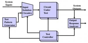
Let’s start with Digital testing as that’s where this all began. The diagram below provides the basic building blocks.
Source Professor Dhingra’s lecture notes for ELEC7250 at Auburn University
Naturally BIST tests run independent of system inputs so you need a means to isolate the circuitry during the test. The ability to control the test execution is provided. The variation then comes in the Test Pattern Generator (TPG) and the Output Response Analyzer (OPA). To maintain a small area cost a designer often implements the TPG following an algorithm. The OPA needs to compare the expected response to the actual response. Typically, it uses an algorithmic implementation.
For Digital testing, BIST implementations require a Scan-based design to handle the sequential circuit elements. The TPG often uses a pseudo-random algorithm to generate a pattern using a Linear Feedback Shift Register (LFSR). Hence, the OPA would implement something similar to compare the results, i.e. another LFSR. However, to save time and area, you commonly find designers use a Multiple Input Signature Register (MISR) which is a very specific type of LFSR. This combines multiple outputs into a signature to be compared. You will learn more about LFSRs and MISRs in future articles.
Not Just for Digital Test
This labor saving DFT is not just restricted to digital circuits. Both memory and analog circuits can use BIST techniques.
The size of patterns motivates using BIST and as pointed out in Memory test introduction you need many patterns to fully test a memory. Memory devices make ideal candidates for BIST due to the algorithmic nature of the patterns (checkboard pattern). When embedded memory became more prevalent memory BIST (aka MBIST) started to appear on die.
So you’re wondering how does analog BIST work—very similar with the challenge being that the stimulus and response will be analog in nature. With mixed-signal devices (digital and analog circuits on the same device) it can be easier. Think about a Digital to Analog Converter (DAC) which has 2**n states. For a computer interface like PCI Express 2.0 pattern generators and comparators exist to enable loopback testing. You can then manipulate analog values of voltage and time to comprehend defects which impact its analog performance.
BIST Questions for You to Ask
In your role as a reliability engineer you need to understand amount of circuitry exercised during a Burn-In test step and you need to know how to root cause to a failing circuit. So when you hear BIST mentioned at the meeting you can ask the following:
- What’s the expected savings in ATE test time?
- What’s the percent area of the BIST compared to the IC design block it is testing?
- How much Fault coverage does it provide for (insert favorite fault model here- you can use S@ as your default)?
- What kind of algorithm is the TPG based upon?
- How do I diagnosis a failure when you have a MISR that is compressing the responses?
- How much toggle coverage does the BIST provide?
Have I left off anything? If so let me know in the comments.
Meanwhile remember testing takes time and thoughtful application,
Anne Meixner, PhD
Additional Reading:
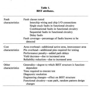
Professor Ed McClusky published two papers in Design and Test of computers that provide basic techniques and the implementations. While BIST has continued to evolve and designers have continued to innovate, these articles provide a very good place to start. The table below is from the techniques paper which summarizes BIST attributes.
For an early (1985) snap-shot at BIST in microprocessors go read Built-In Self-Test Trends in Motorola Microprocessors.
The oldest relevant article in the IEEE data base is from August 1963 and is entitled Self-Test of Digital Evaluation Equipment. I have provided you the abstract below.
Digital Evaluation Equipment (DEE) is a programmer-controlled concept for building block test equipment. A particular system consists of a computer/controller, measuring system, stimulus generators and power supplies. DEE self-test utilizes a dual function concept; (1) automatically programmed testing, and (2) individual self-test of each building block. Since a DEE system encompasses a large test capability, the equipment is complex and design efforts have been concentrated on optimum use of the system to check itself. Self-test design is divided into the areas of systems testing and monitoring techniques. The programmed system testing uses the measuring equipment’s in the system to determine the operability of the various stimuli generators. The measurement unit is automatically self-calibrated with internal standards to assure that the system accuracy is maintained. The computer is self-tested using magnetic and/or paper tape depending on the degree of malfunction. The design of the programmed self-test is based on automation of all basic test functions that can be reduced to hardware without greatly increased complexity. Manual operations using military personnel are minimized. Self-test circuits are described for monitoring both digital and analog parameters. The types of circuits are described along with the criteria of their selection to perform the monitoring functions.


 Ask a question or send along a comment.
Please login to view and use the contact form.
Leave a Reply