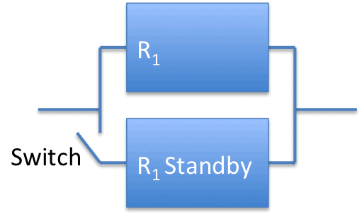
First off, switches are not perfect, so this situation is hypothetical. Yet, when you are exploring adding standby redundancy and haven’t sorted out the switching mechanism, you may be purely curious about the benefits of the redundancy.
Second, in practice, we use different equipment or components for the standby redundancy.
For example, we may use a diesel generator as a backup for grid power. Or use a refurbished pump to back up the main pump. Consider this situation for standby redundancy with equal failure rates (same type and age equipment) and a perfect ability to detect and turn on the backup unit as an exercise that leads to other realistic cases.
Let’s explore the math to estimate the system reliability given standby redundancy with an example.
Two power supply systems with one supply in standby
The two supplies have the same expected failure rate, 0.0005 failures per hour, over the duration we expect the system to operate, 730 hours. Only one operates at a time. And, we’re going to ignore how the second supply is turned on when the first one fails for now. We’re assuming a perfect switch.
Here’s a simple diagram of the situation.

Where R1 is the reliability function of the power supplies. So, what is the reliability expectation of this standby redundancy configuration?
The formula for we can use in this situation is
$$ \large\displaystyle R\left( t \right)={{e}^{-\lambda t}}\left( 1+\lambda t \right)$$
This is slightly different then the k-out-of-n formula with a 1-out-of-2 situation as the first unit operates alone while the standby unit is dormant and assumed to have not dormant failure period failures.
Adding the values for t and $- \lambda -$ we find
$$ \large\displaystyle \begin{array}{l}R\left( 730 \right)={{e}^{-\left( 0.0005 \right)730}}\left( 1+\left( 0.0005 \right)730 \right)\\R\left( 730 \right)={{e}^{-0.365}}\left( 1.365 \right)\\R\left( 730 \right)=0.948\end{array}$$
A general formula
In the case with n standby units each with a perfect switch when the previous elements have failed, the general formula is
$$ \large\displaystyle R\left( t \right)={{e}^{-\lambda t}}\sum\limits_{i=0}^{n-1}{\frac{{{\left( \lambda t \right)}^{i}}}{i!}}$$
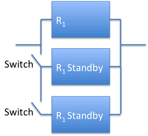
Here’s a simple diagram of a system with n=3. Note the second standby units doesn’t become active until the primary and first standby units fail. After the unit brought online by the first switch fails, the second switch closes allowing the system to operate with the second standby unit.

You may envision n such standby switches and units in a configuration. Now you can calculate the system reliability for these standby parallel situations.
Related:
Standby Redundancy, Equal Failure Rates, Imperfect Switching (article)
Parallel Systems (article)
RBD and Design Process (article)
 Ask a question or send along a comment.
Please login to view and use the contact form.
Yes, this is for perfect switching. In case of imperfect switching you need to just multiply the probability of failure of that imperfect switch with the equation you have provided. But, have you experienced it by iterating 1000 times through Monte-carlo simulation. I mean the result.What results did you get.
Thanks for the comment Sameer,
I’ve not tried the Monte Carlo approach and will have to explore it later. For some cases it is possible to analytically solve for system reliability including imperfect switching, which is the topic of another post.
Cheers,
Fred
I’m trying to understand the rationale behind the computation. Can you provide a derivation of the formula? Fifty years ago I was a reliability engineer in my first job. At the time we focused on active redundancy because of the state of failure detection and switching technology.
HI Dick,
I found a reasonable explanation in
Reliability in Engineering Design ” target=”_blank”>Reliability in Engineering Design by Kailash C. Kapur. Wiley, 1977 pg 218-221 [affiliate link to Amazon]
Here are the scanned pages from my copy. You will need to be logged into Accendo Reliability to download.
Cheers,
Fred
Hello,
Is it possible to be directed to a derivation for this? I generally understand how to set-up the problem for a duty/stand-by system but can’t get over the hump of fully solving it.
Regards,
Aaron
Hi Aaron,
good question – most of my references just include the formulas for the various situations with perfect or imperfect switches. A general derivation might start with thinking through the probabilities involved and how to combine them. An imperfect switch would be in series with the second unit, I suppose.
Cheers,
Fred
Hello Fred,
is there a formula or referenced that you can point me to for when active and standby units have different failure rates?
Thank you,
Farid
Hi Farid,
I haven’t written about such a case and a quick check of a couple of the reference books I have hasn’t turned up such a case. It is a good idea, so will add to my list of topics to research and write a short tutorial.
cheers,
Fred
I found this article while i search generator reliability. In case of any power failure, the generator is activated, in this case is always generator redundant a system? When the generator is used in this way, is it a subsystem that always increases the reliability of the system?
Thank for all informations.
ayca
Hi Ayca,
The reliability of the various elements of the system don’t really change – the redundant elements improve the availability of the overall system.
At the overall system level, with the generator, the ability (probability) of the system to provide power (function) over time in the specified environment has an improved reliability performance. The tradeoff comes with a more complex system and an increased cost of maintenance.
cheers,
Fred
Unfortunately, there is no simple elementary way to derive the general formula. But the following reasoning may help to understand it. Consider the case with perfect switching, for now, with one standby, and equal failure rates. R(t) = Prob (system survives up to t) = Prob(first element survives up to t) + Prob(first elements fails at some point x before t, and the second element survives for the remaining time t – x) = exp(-λt) + Sum over possible x between 0 and t[ λexp(-λx) Δx exp(-λ(t-x))] = exp(-λt) + λexp(-λt) * Sum over sum over possible x between 0 and t [Δx] = exp(-λt) + λexp(-λt) t = exp(-λt)[1 + λt]. Here, λexp(-λx) Δx is the probability that the first unit fails in a short interval Δx (using pdf for exponential distribution). Mathematically, summation is replaced by integration. For the case with imperfect switch, the same derivation, except we have to include probability of successful switching, p, after failure of the first element, so the formula is R(t) = exp(-λt)[1 + λpt]. For cases with more than one element, problem gets more complicated, because we have several situations: no failure of the first element up to t, or failure of the first element before t, and survival of the second element to t, or failures of the first and second element before t, and survival of the third element to t, and so on, up to the last element. Integration step by step will solve the problem. Exactly the same reasoning works with different failure rates, but the formula is more complicated.
It’s an interesting topic to go through. I was wondering about the mixed redundancy, i.e. some components are actively redundant and others are on standby. Can you explain the reliability function of such systems? It would be very helpful.
Thank you.
HI Ashok,
In a mixed redundancy setup – I would treat the active redundancy elements first as one system, then use the result of the active elements and the standby elements as a second system to do the calculations.
cheers,
Fred