FMEA Q and A
In this Q and A article, a reader asks a challenging question about the linkage between FMEA boundary diagrams and Design FMEAs. There are many linkages between different elements of FMEAs, and this question/answer highlights one of the key linkages.
“In all affairs, it’s a healthy thing to hang a question mark on the thing you have long taken for granted.”
Bertrand Russell
Reader’s Question
How do “boundary diagrams” and “interface matrices” link to DFMEA? Could you please share experience regarding how using “boundary diagrams” and “interface matrices” help to improve FMEA process, and identify important functions?
Answer to Reader’s Question
An FMEA boundary diagram (also called an “FMEA block diagram”) is an essential input to new FMEA projects. It is a visual depiction of the entire system or design to show clearly the boundaries of the FMEA analysis (what is included and not included), the interfaces between the items, and other information that can help to depict the scope of the FMEA. The functions of the FMEA must be within the scope of the diagram, and include all of the interfaces that are identified.
An FMEA Interface Matrix, on the other hand, is an optional input to System or Subsystem FMEAs. It is a chart with the subsystems and/or components (depending on the scope of the FMEA) on both the vertical and horizontal axes, and clearly shows which interfaces must be considered in the analysis and the type of interface. It is done when the FMEA team wants to ensure that all of the various types of interfaces are included in the analysis, missing none. The functions of the FMEA must include all of the identified interfaces.
The key linkage between FMEA boundary/block diagram, FMEA interface matrix and Design FMEA is interfaces. Each interface in the FMEA boundary/block diagram and/or the FMEA interface matrix has a one-to-one linkage to a corresponding function in the Design FMEA.
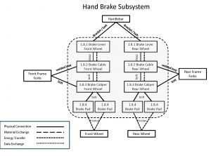
For example, consider the fictional bicycle hand brake FMEA Block Diagram shown in Figure 1.
Figure 1
Let’s take the interface between 1.8.3 Brake Caliper and 1.8.4 Brake Pad. The interface is a bolt (physical connection). In the Design FMEA for the Hand Brake Subsystem, one of the functions could be “Interface Brake Caliper – Brake Pad: the bolt provides secure connection between brake caliper and brake pad, with no movement during all anticipated bicycle maneuvers.”
Next Article
Does a cause description need to be a design or manufacturing deficiency? Why? This is one of the more important questions to consider if you want to achieve quality FMEAs. In next week’s article, this question will be answered, along with essential information about identifying and applying “causes” in FMEAs.

 Ask a question or send along a comment.
Please login to view and use the contact form.
Leave a Reply